For many automotive enthusiasts and tech hobbyists, the intersection of cars and coding is a fascinating space. While we often engage with software and digital systems, the underlying electronics that power these systems can seem like a mystery. The idea that electronics are complex and require specialized engineering degrees is a common misconception. As a car repair expert and coding aficionado, I’ve always been intrigued by Arduino and the possibilities it unlocks. Like many, I had a remote control (RC) car in my childhood and dreamed of building my own as an adult. Combining my growing coding skills with an Arduino kit presented the perfect opportunity to bring this childhood dream to life.
This guide will walk you through creating an Arduino-based RC car from scratch. No prior experience in programming, Arduino, or electronics is necessary. While any background in these areas can be beneficial, these instructions are designed for beginners. You might wonder about the use of a power bank for this project. Power banks are now readily available and affordable, often less expensive than traditional batteries. They are reusable, rechargeable, and many of us already have them at home. This project focuses on the fundamental principles of building such a car, using readily available materials and providing a detailed explanation of the code. The principles you learn here can also be applied to a wide range of other projects. Let’s get started and have some fun!
As a hobbyist, I aimed for simplicity and accessibility, utilizing common household items like USB cables and power banks. Feel free to follow these instructions closely or adapt them to your own creative vision. Here’s a list of the materials you will need:
- Arduino UNO
- Car chassis kit (including wheels and motors)
- Jumper wires (male-male and female-male)
- Electrical insulation tape
- Bluetooth module (HC-06 or HC-05)
- DC motor controller (L298N)
- Power Bank with 2 USB outputs
- Piezo buzzer
- Android mobile phone
- PC with Arduino IDE installed
- ArduCar – Arduino RC Car Bluetooth Controller App
Step 1: Chassis Assembly
The first step is to assemble the chassis of your toy car. If you purchased a kit, it likely includes assembly instructions. However, here are the basic steps to guide you:
- Gather the main chassis components: the chassis frame, four small plastic motor brackets (two for each motor), screws, brass spacers, nuts, motors, a spare USB cable, and four jumper wires.
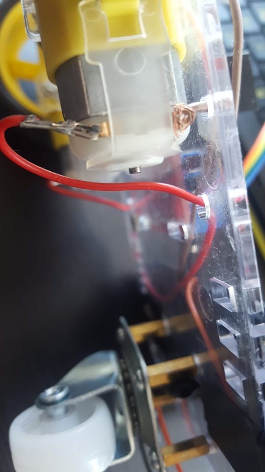
- Connect a jumper wire to each terminal of both motors. Soldering provides a robust connection, but for beginners without soldering equipment, securely twisting or “knotting” the wires to the motor terminals will suffice.
Image alt text: Close-up of a DC motor with jumper wires connected to its terminals, demonstrating the initial wiring step in toy car assembly.
- Take an old USB cable and cut off one end, leaving approximately 20 cm (around 8 inches) of cable.
- Carefully strip a few centimeters of the outer cable insulation to expose the internal wires. You should find several wires inside, but we are primarily interested in the black (GND – Ground) and red (VCC – Power) wires. Strip about 2-4 cm of insulation from the ends of the red and black wires. You can use these as is or reinforce them by twisting or soldering them to longer, more durable jumper wires for a more secure connection.
Image alt text: Image showing a USB cable that has been cut and stripped, revealing the red and black power wires for use in the toy car’s power supply.
- Mount the motors to the chassis frame using the plastic brackets, screws, and nuts. Each motor usually has a small dot on one side. Ensure that these dots face inwards towards each other when both motors are mounted. This orientation is important for consistent motor direction.
Image alt text: Toy car chassis with DC motors attached using plastic brackets, showcasing the motor mounting process.
- Locate the four small holes arranged in a square near the end of the chassis frame. These are for the supporting nylon wheel. Attach brass spacers to these holes using screws, ensuring the spacers are on the same side of the frame as the motors.
- Mount the nylon supporting wheel to the brass spacers using screws. This wheel provides stability to the car.
Image alt text: Close-up view of the nylon supporting wheel being mounted to the chassis using brass spacers, highlighting the rear wheel assembly.
- Attach the drive wheels to each motor shaft. Notice the shape inside the wheel hub, which should align with the motor shaft. You might encounter some resistance when pushing the wheels onto the shafts, but apply firm, gentle pressure until they are securely in place.
- At this stage, you can mount the Arduino UNO board and the L298N DC motor controller onto the chassis frame. Use screws and nuts from your kit or other suitable fasteners. Use electrical tape to insulate any exposed wires and secure components.
Image alt text: Toy car chassis with Arduino UNO and L298N motor controller board mounted on top, ready for wiring connections.
Step 2: Wiring
With the chassis assembled and the electronic components mounted, it’s time to connect everything. Prepare your male-male and female-male jumper wires.
-
Connect the wires from the motors to the L298N DC motor controller. The L298N controller has terminals labeled OUT1, OUT2, OUT3, and OUT4 for motor connections. Typically, the pins closer to the edge of the board are considered ground (-) and the inner pins are positive (+). Connect them as follows:
- OUT1: Left motor (-) GND wire
- OUT2: Left motor (+) wire
- OUT3: Right motor (+) wire
- OUT4: Right motor (-) GND wire
Image alt text: Wiring diagram showing motor wires connected to the OUT terminals of the L298N motor controller for controlling the toy car’s motors.
-
Now, connect the Arduino UNO to the DC motor controller. Use the pins labeled IN1, IN2, IN3, and IN4 on the L298N. These pins will receive control signals from the Arduino to drive the motors. You’ll likely need female-male jumper wires for these connections.
- IN1: Arduino Digital Pin 5
- IN2: Arduino Digital Pin 6
- IN3: Arduino Digital Pin 10
- IN4: Arduino Digital Pin 11
-
Connect the Bluetooth module (HC-06 or HC-05). These modules usually have four pins: VCC (Power), GND (Ground), TXD (Transmit Data), and RXD (Receive Data). Female-male jumper wires will likely be needed here as well. Data transmission requires cross-connection: the Bluetooth module’s TXD connects to the Arduino’s RXD, and vice versa.
- Bluetooth VCC: Arduino 5V pin
- Bluetooth GND: Arduino GND pin
- Bluetooth TXD: Arduino Digital Pin 0 (RXD)
- Bluetooth RXD: Arduino Digital Pin 1 (TXD)
Image alt text: Diagram showing the Bluetooth module (HC-06) wired to the Arduino UNO board, including power and data transmission connections.
-
Connect the piezo buzzer. Piezo buzzers have two pins: a longer Anode (+) pin and a shorter Cathode (-) pin. While a 330 Ohm resistor is typically recommended between the Anode and the Arduino to limit current and protect the buzzer, it can significantly reduce the buzzer’s volume. For this project, you can connect it directly.
- Piezo Anode (+) (Longer leg): Arduino Digital Pin 3
- Piezo Cathode (-) (Shorter leg): Arduino GND pin
Image alt text: Image showing the piezo buzzer connected to the Arduino board, illustrating the positive and negative pin connections for sound output.
-
Powering the circuit. Use the USB cable section you prepared earlier to power both the Arduino and the DC motor controller. Connect the red (+) and black (-) wires to the L298N motor controller’s power input terminals.
- Red wire (+): L298N 12V terminal
- Black wire (-): L298N GND terminal
-
Finally, connect two USB cables to your power bank. One cable connects the power bank to the Arduino board (for Arduino power). The other cable connects the power bank to the USB wires leading to the DC motor controller (for motor power). Secure the power bank to the chassis using electrical tape or another mounting method. Note that some power banks require you to press a power button to activate the output.
Image alt text: Circuit diagram illustrating the complete wiring setup of the Arduino RC toy car, showing connections between Arduino, motor controller, Bluetooth module, buzzer, and power source.
- With all components wired, the hardware setup is complete. The next step is to program the Arduino and install the control application.
Step 3: Programming the Arduino
Now, let’s get to the core of “How To Program A Toy Car”—uploading the control code to the Arduino board. You’ll need the Arduino IDE (Integrated Development Environment) software installed on your computer, which can be downloaded from the official Arduino website.
- Configure Arduino IDE: Open the Arduino IDE. Go to “Tools” in the menu bar. Select “Board:” and choose your Arduino board (usually Arduino UNO). Then, select “Port:” and choose the USB port your Arduino is connected to. If the “Port” option is grayed out, connect your Arduino to your computer via USB and wait for the port to become available. You may need to try different USB ports on your computer until the Arduino is recognized.
Image alt text: Screenshot of the Arduino IDE showing the “Tools” menu open, highlighting the “Board” and “Port” settings for configuring the software.
-
Upload the Code: You have two options for getting the code into the Arduino IDE:
a. Download and Open: Download the provided Arduino code file (if available as a separate file). Open the file directly in the Arduino IDE.
b. Copy and Paste: Copy the code provided below. In the Arduino IDE, go to “File” > “New” to create a new sketch. Paste the code into the new sketch window. -
Upload to Arduino: Click the “Upload” button (usually a right-arrow icon) in the Arduino IDE.
Important Note: Disconnect the Bluetooth module’s RX (Digital 0) and TX (Digital 1) wires from the Arduino before uploading the code. These connections can interfere with the code upload process. Reconnect them after the upload is complete.
Here is the Arduino code for controlling your toy car:
#define in1 5
#define in2 6
#define in3 10
#define in4 11
int state;
int piezo = 3;

void setup() {
  pinMode(in1, OUTPUT);
  pinMode(in2, OUTPUT);
  pinMode(in3, OUTPUT);
  pinMode(in4, OUTPUT);
  pinMode(piezo,OUTPUT);
  Serial.begin(9600);
}

void loop() {
  if (Serial.available() > 0) {
    state = Serial.read();
    Stop();
    switch (state) {
      case 'F': forward(); soundFX(3000.0,30+400*(1+sin(millis()/5000))); break;
      case 'G': forwardleft(); soundFX(3000.0,60); break;
      case 'D': forwardright(); soundFX(3000.0,60); break;
      case 'N': backright(); soundFX(3000.0,30+100*(1+sin(millis()/2500))); break;
      case 'C': backleft(); soundFX(3000.0,30+100*(1+sin(millis()/2500))); soundFX(3000.0,30+100*(1+sin(millis()/2500))); soundFX(3000.0,30+100*(1+sin(millis()/2500))); soundFX(3000.0,30+100*(1+sin(millis()/2500))); break;
      case 'B': back(); soundFX(3000.0,30+200*(1+sin(millis()/2500))); soundFX(3000.0,30+200*(1+sin(millis()/2500))); soundFX(3000.0,30+200*(1+sin(millis()/2500))); soundFX(3000.0,30+200*(1+sin(millis()/2500))); break;
      case 'L': left(); soundFX(3000.0,60); soundFX(3000.0,60); soundFX(3000.0,60); soundFX(3000.0,60); break;
      case 'R': right(); soundFX(3000.0,60); soundFX(3000.0,60); soundFX(3000.0,60); soundFX(3000.0,60); break;
      case 'H': soundFX(3000.0,30+200*(1+sin(millis()/2500))); soundFX(3000.0,60); soundFX(3000.0,30+200*(1+sin(millis()/2500))); soundFX(3000.0,60); break;
    }
  }
}

void forward() {
  analogWrite(in1, 255);
  analogWrite(in3, 255);
}

void forwardleft() {
  analogWrite(in1, 50);
  analogWrite(in3, 255);
}

void forwardright() {
  analogWrite(in1, 255);
  analogWrite(in3, 50);
}

void back() {
  analogWrite(in2, 255);
  analogWrite(in4, 255);
}

void backright() {
  analogWrite(in2, 50);
  analogWrite(in4, 255);
}

void backleft() {
  analogWrite(in2, 255);
  analogWrite(in4, 50);
}

void left() {
  analogWrite(in4, 255);
  analogWrite(in1, 255);
}

void right() {
  analogWrite(in3, 255);
  analogWrite(in2, 255);
}

void Stop() {
  analogWrite(in1, 0);
  analogWrite(in2, 0);
  analogWrite(in3, 0);
  analogWrite(in4, 0);
}

void soundFX(float amplitude,float period){
  int uDelay=2+amplitude+amplitude*sin(millis()/period);
  for(int i=0;i<200;i++){
    digitalWrite(piezo, HIGH);
    delayMicroseconds(uDelay);
    digitalWrite(piezo, LOW);
    delayMicroseconds(uDelay);
  }
}-
Reconnect and Power On: After successful code upload, reconnect the Bluetooth module’s RX and TX wires to the Arduino. Reconnect the USB cable from the Arduino to the power bank to power the circuit.
-
Install the Control App: Download the ArduCar – Arduino RC Car Bluetooth Controller app from the Google Play Store on your Android phone. Launch the app and follow its instructions to connect to your toy car via Bluetooth. You can also explore other Bluetooth RC car control apps that send compatible serial commands or even develop your own app for a customized experience.
Image alt text: Screenshot of the ArduCar Android application interface, showing the controls for operating the Arduino-powered toy car via Bluetooth.
Congratulations! You have now built and programmed your own Arduino-controlled toy car. Have fun experimenting and driving your creation!
Step 4: Understanding the Arduino Code
For those interested in delving deeper into the code and understanding how it works, here’s a breakdown of the Arduino sketch:
Every Arduino program has two essential functions: setup() and loop().
-
void setup() { }: This function runs once at the beginning of the program. It’s used to initialize settings, define pin modes, and start serial communication.pinMode(in1, OUTPUT);,pinMode(in2, OUTPUT);, etc.: These lines configure digital pins 5, 6, 10, 11, and 3 as OUTPUT pins. These pins will send signals to control the motor driver and the piezo buzzer.in1,in2,in3,in4, andpiezoare symbolic names assigned to these pins using#defineat the beginning of the code, making the code more readable.Serial.begin(9600);: This line initializes serial communication at a baud rate of 9600 bits per second. This is how the Arduino communicates with the Bluetooth module to receive commands from your Android phone. 9600 is a common and reliable baud rate for Bluetooth communication.
-
void loop() { }: This function runs continuously after thesetup()function completes. It contains the main logic of your program, constantly checking for input and controlling the car’s actions.if (Serial.available() > 0) { ... }: This checks if there is any data available to be read from the serial port (i.e., from the Bluetooth module).state = Serial.read();: If data is available, this line reads the first byte of serial data and stores it in thestatevariable. Thisstatevariable represents the command received from the Bluetooth control app.Stop();: Before executing any movement command, theStop()function is called to ensure the car stops before performing a new action. This prevents commands from overlapping.switch (state) { ... }: Thisswitchstatement checks the value of thestatevariable and executes different functions based on the received command character.case 'F': forward(); soundFX(...); break;: If the received character is ‘F’, theforward()function is called to move the car forward, andsoundFX()function is called to play a sound. Similarcasestatements handle commands ‘G’ (forward-left), ‘D’ (forward-right), ‘N’ (back-right), ‘C’ (back-left), ‘B’ (back), ‘L’ (left), ‘R’ (right), and ‘H’ (special sound effect).break;: Thebreakstatement exits theswitchblock after acaseis executed, preventing fall-through to the next case.
-
Movement Functions (
forward(),back(),left(),right(),forwardleft(),forwardright(),backleft(),backright(),Stop()):- These functions define how to control the motors to achieve different movements. They use
analogWrite(pin, speed)to control the speed and direction of each motor connected to the L298N motor driver. analogWrite()is used because it allows for Pulse Width Modulation (PWM), which effectively controls the voltage supplied to the motors, thus controlling their speed. The speed value ranges from 0 (stopped) to 255 (full speed).- By controlling the voltage to each motor independently, we can achieve forward, backward, left, right, and combined movements. For example,
forward()function sets both motors to move forward at full speed (255).left()function might stop or reverse one motor while powering the other to turn left.
- These functions define how to control the motors to achieve different movements. They use
-
void soundFX(float amplitude, float period) { ... }:- This function generates a sound effect using the piezo buzzer. It’s based on code found in Arduino forums for generating Sci-Fi sounds.
- It uses
digitalWrite(piezo, HIGH)anddigitalWrite(piezo, LOW)to rapidly turn the piezo buzzer on and off, creating sound waves.delayMicroseconds()controls the duration of the on/off pulses, and theamplitudeandperiodparameters control the characteristics of the sound. - The formula
int uDelay=2+amplitude+amplitude*sin(millis()/period);dynamically changes the delay based on sine wave, creating varying tones.
This detailed explanation should give you a solid understanding of the Arduino code and how it controls your toy car. Feel free to experiment with the code, modify speeds, add new sound effects, or even create new movement patterns.
Step 5: (Optional) Bluetooth Configuration
HC-05 and HC-06 Bluetooth modules typically come with default settings like baud rate, name, and password. However, if you need to customize these settings, you can configure the Bluetooth module using the Arduino IDE. This process usually involves connecting the Bluetooth module to the Arduino in a specific configuration and uploading a configuration sketch. It’s important to note that Bluetooth modules often operate at 3.3V logic levels, while Arduino operates at 5V. For robust configuration, it’s recommended to use voltage dividers (resistors) on the data lines between the Arduino and the Bluetooth module to prevent damage. Numerous online tutorials provide detailed steps for configuring Bluetooth modules with Arduino. Search for “HC-06 Arduino configuration” or “HC-05 Arduino configuration” for step-by-step guides.
We encourage you to share your own toy car projects and modifications in the comments below! If you have any questions or suggestions, please feel free to ask. Happy building and programming!