Many people are fascinated by the world of coding, yet often perceive electronics as a complex and daunting field, typically reserved for engineers. However, the truth is that electronics, the very foundation of our digital world, are more accessible than you might think. For car enthusiasts, tech lovers, and coding beginners alike, combining these interests can lead to exciting projects. If you’ve ever dreamt of building your own remote control car and understanding how to program its every move, you’re in the right place. This guide will walk you through creating an Arduino-based RC car from scratch, even if you have no prior experience in programming, Arduino, or electronics.
Think back to childhood dreams of RC cars racing around. Now, imagine not just controlling one, but building and programming it yourself! With readily available and affordable components like Arduino and Bluetooth modules, coupled with everyday items like a power bank, this dream is easily within reach. This tutorial provides a step-by-step approach to constructing your own programmable RC car. We’ll focus on a minimalist approach to materials, clear instructions, and a detailed explanation of the Arduino code, ensuring that even absolute beginners can successfully complete this project and learn valuable skills applicable to countless other DIY electronics endeavors. Let’s get started and bring this exciting project to life!
Here’s what you’ll need to gather to embark on this exciting project. You might even have some of these components lying around!
- Arduino UNO board: The brain of your RC car, programmable and versatile.
- RC Car Chassis Kit: Includes the base, wheels, and motors – the physical foundation of your car.
- Jumper Wires (male-male and female-male): For connecting electronic components neatly and easily.
- Electrical Insulation Tape: To ensure secure and insulated wire connections.
- Bluetooth Module (HC-06 or HC-05): Enables wireless control of your car via Bluetooth.
- DC Motor Controller (L298N): The power regulator that drives the car’s motors.
- Power Bank (with dual USB outputs): Provides a portable and rechargeable power source for your project.
- Piezo Buzzer: For adding fun sound effects to your RC car.
- Android Mobile Phone: To install the control application and wirelessly operate your car.
- PC with Arduino IDE Installed: Your coding station to program the Arduino board.
- ArduCar – Arduino RC Car Bluetooth Controller App: A ready-made Android app for controlling your RC car, or you can explore others!
Step 1: Assembling the RC Car Chassis
Let’s start by building the physical foundation of our RC car – the chassis. Most chassis kits come with their own assembly instructions, which are always a good place to begin. However, if you need a little extra guidance, follow these steps to get your chassis ready:
-
Prepare the Components: Gather the main chassis frame, motor mounting brackets (usually four small plastic pieces, two for each motor), screws, brass spacers, nuts, the DC motors, a spare USB cable, and four jumper wires.
-
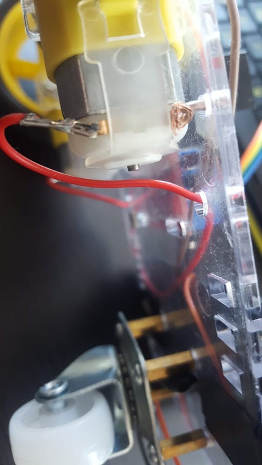
Connect Wires to Motors: Attach a jumper wire to each terminal of both DC motors. Soldering provides the most secure connection, but if you don’t have a soldering iron, you can carefully twist or “knot” the wires firmly around the motor pins to ensure good contact.
-
Prepare the USB Cable for Power: Take an old USB cable and cut off one end, leaving about 20cm (8 inches) of cable length with the USB connector.
-
Expose Power Wires: Carefully strip a few centimeters of the outer insulation of the cut end of the USB cable to reveal the internal wires. You should see several wires inside, but we’re only interested in two: the ground wire (usually black) and the power wire (+5V, usually red). Strip about 2-4 cm of insulation from the ends of both the red and black wires. For a more robust connection, you can twist these exposed ends with longer, stronger jumper wires or solder them.
-
Mount Motors to Chassis: Attach the DC motors to the chassis frame using the plastic brackets, screws, and nuts. Most motor kits have a small dot or marking on one side of each motor. Ensure these dots are facing inwards, towards each other, when both motors are mounted. This ensures consistent motor directionality.
-
Install Supporting Wheel: Locate the set of four small holes, usually in a square pattern, at the rear of the chassis frame. These are for the supporting nylon wheel. Use the brass spacers and screws to mount the spacers to these holes, positioning them on the same side of the frame as the motors.
-
Attach Nylon Wheel: Mount the nylon supporting wheel to the brass spacers using screws. This wheel provides stability and prevents the car from dragging.
- Mount Wheels and Electronic Boards: Push the wheels onto the motor shafts. You might encounter some resistance, but apply firm, gentle pressure to ensure they are securely fitted. Finally, position the Arduino UNO board and the L298N DC motor controller on the chassis frame. Use screws and nuts from your kit to secure them. Electrical tape can be used to neatly organize and secure any loose wires at this stage.
Step 2: Wiring the Electronics
With the chassis assembled and the electronic boards mounted, it’s time to connect everything. This step involves using jumper wires to create the necessary circuits. Have your male-male and female-male jumper wires ready.
-
Connect Motors to Motor Controller: Take the wires you connected to the motors in Step 1 and attach them to the L298N DC motor controller. The motor controller has screw terminals labeled OUT1, OUT2, OUT3, and OUT4. Typically, the terminals closer to the edge of the board are considered negative (-) or ground (GND), and the inner ones are positive (+). Connect them as follows:
- OUT1: Left Motor (-) GND wire
- OUT2: Left Motor (+) wire
- OUT3: Right Motor (+) wire
- OUT4: Right Motor (-) GND wire
-
Connect Arduino to Motor Controller: Now we need to link the Arduino to the motor controller to send commands. Use female-male jumper wires for these connections. The L298N has input pins labeled IN1, IN2, IN3, and IN4. Connect them to the Arduino digital pins as follows:
- L298N IN1 to Arduino Digital Pin 5
- L298N IN2 to Arduino Digital Pin 6
- L298N IN3 to Arduino Digital Pin 10
- L298N IN4 to Arduino Digital Pin 11
-
Connect Bluetooth Module: The Bluetooth module (HC-06 or HC-05) allows wireless communication. It typically has four pins: VCC (Power), GND (Ground), TXD (Transmit Data), and RXD (Receive Data). Use female-male jumpers to connect it to the Arduino:
- Bluetooth VCC to Arduino 5V pin
- Bluetooth GND to Arduino GND pin
- Bluetooth TXD to Arduino Digital Pin 0 (RXD)
- Bluetooth RXD to Arduino Digital Pin 1 (TXD)
Notice that the TXD and RXD pins are cross-connected. This is because TX (transmit) from one device needs to connect to RX (receive) of the other for data exchange.
-
Connect Piezo Buzzer (Optional): If you want sound effects, connect the piezo buzzer. It has two legs: a longer one (Anode, +) and a shorter one (Cathode, -). While a 330 Ohm resistor is often recommended in series with the piezo buzzer to limit current, it can sometimes make the buzzer very quiet. For this project, we’ll connect it directly for louder sound effects. Connect it as follows:
- Piezo Buzzer Anode (long leg) to Arduino Digital Pin 3
- Piezo Buzzer Cathode (short leg) to Arduino GND pin
-
Powering the Motor Controller: Use the USB cable you prepared in Step 1. Connect the red wire (+) to the 12V terminal on the L298N motor controller and the black wire (-) to the GND terminal.
-
Powering the Circuit: Finally, connect two USB cables. One cable connects your power bank to the Arduino UNO (via the USB port on the Arduino). The second USB cable, the one connected to the L298N motor controller, also connects to the power bank. This setup powers both the Arduino and the motor controller from the same power source. Secure the power bank to the chassis using electrical tape or another mounting method. Note that some power banks have a power button that you may need to switch on to activate the power output.
With all the wiring complete, the hardware assembly is done. The next crucial step is programming the Arduino to control your RC car!
Step 3: Programming Your RC Car with Arduino IDE
Now for the exciting part – bringing your RC car to life with code! We’ll use the Arduino IDE (Integrated Development Environment) to program the Arduino board. If you haven’t already, download and install the Arduino IDE from the official Arduino website.
Once installed and opened, you need to configure the IDE for your Arduino board.
- Select Your Board and Port: In the Arduino IDE, go to “Tools” in the top menu. Hover over “Board:” and select “Arduino Uno” (or whichever Arduino board you are using) from the list. Then, go back to “Tools” and hover over “Port:”. Connect your Arduino board to your computer using a USB cable. The “Port:” option should become active, listing available serial ports. Select the port that corresponds to your Arduino board (it may be labeled or you might need to experiment to find the correct one – on Windows, it often appears as COM followed by a number; on macOS and Linux, it’s usually something like /dev/ttyACM or /dev/ttyUSB).
-
Upload the Code: You have two ways to get the code into the Arduino IDE:
a. Download and Open: Download the provided Arduino code file (if available, often as a
.inofile). Open it in the Arduino IDE – typically by going to File > Open and selecting the downloaded file.b. Copy and Paste: Alternatively, create a new sketch in the Arduino IDE (File > New). Copy the code provided below and paste it into the new sketch window.
Important Note: Before uploading the code, disconnect the Bluetooth module’s TX and RX pins (Digital 0 and Digital 1) from the Arduino. Leaving them connected can interfere with the code upload process, potentially causing the upload to fail or the Arduino IDE to freeze at the “uploading” stage.
Here’s the Arduino code you’ll need to program your RC car. This code is designed to receive commands via Bluetooth and control the motors and piezo buzzer accordingly.
#define in1 5
#define in2 6
#define in3 10
#define in4 11
int state;
int piezo = 3;

void setup() {
  pinMode(in1, OUTPUT);
  pinMode(in2, OUTPUT);
  pinMode(in3, OUTPUT);
  pinMode(in4, OUTPUT);
  pinMode(piezo,OUTPUT);
  Serial.begin(9600);
}

void loop() {
  if (Serial.available() > 0) {
    state = Serial.read();
    Stop();
    switch (state) {
      case 'F': forward(); soundFX(3000.0,30+400*(1+sin(millis()/5000))); break;
      case 'G': forwardleft(); soundFX(3000.0,60); break;
      case 'D': forwardright(); soundFX(3000.0,60); break;
      case 'N': backright(); soundFX(3000.0,30+100*(1+sin(millis()/2500))); break;
      case 'C': backleft(); soundFX(3000.0,30+100*(1+sin(millis()/2500))); soundFX(3000.0,30+100*(1+sin(millis()/2500))); soundFX(3000.0,30+100*(1+sin(millis()/2500))); soundFX(3000.0,30+100*(1+sin(millis()/2500))); break;
      case 'B': back(); soundFX(3000.0,30+200*(1+sin(millis()/2500))); soundFX(3000.0,30+200*(1+sin(millis()/2500))); soundFX(3000.0,30+200*(1+sin(millis()/2500))); soundFX(3000.0,30+200*(1+sin(millis()/2500))); break;
      case 'L': left(); soundFX(3000.0,60); soundFX(3000.0,60); soundFX(3000.0,60); soundFX(3000.0,60); break;
      case 'R': right(); soundFX(3000.0,60); soundFX(3000.0,60); soundFX(3000.0,60); soundFX(3000.0,60); break;
      case 'H': soundFX(3000.0,30+200*(1+sin(millis()/2500))); soundFX(3000.0,60); soundFX(3000.0,30+200*(1+sin(millis()/2500))); soundFX(3000.0,60); break;
    }
  }
}

void forward() {
  analogWrite(in1, 255);
  analogWrite(in3, 255);
}

void forwardleft() {
  analogWrite(in1, 50);
  analogWrite(in3, 255);
}

void forwardright() {
  analogWrite(in1, 255);
  analogWrite(in3, 50);
}

void back() {
  analogWrite(in2, 255);
  analogWrite(in4, 255);
}

void backright() {
  analogWrite(in2, 50);
  analogWrite(in4, 255);
}

void backleft() {
  analogWrite(in2, 50);
  analogWrite(in4, 50);
}

void left() {
  analogWrite(in4, 255);
  analogWrite(in1, 255);
}

void right() {
  analogWrite(in3, 255);
  analogWrite(in2, 255);
}

void Stop() {
  analogWrite(in1, 0);
  analogWrite(in2, 0);
  analogWrite(in3, 0);
  analogWrite(in4, 0);
}

void soundFX(float amplitude,float period){
  int uDelay=2+amplitude+amplitude*sin(millis()/period);
  for(int i=0;i<200;i++){
    digitalWrite(piezo, HIGH);
    delayMicroseconds(uDelay);
    digitalWrite(piezo, LOW);
    delayMicroseconds(uDelay);
  }
}-
Upload the Sketch: With the code in the Arduino IDE and the Bluetooth module disconnected, click the “Upload” button (the right-arrow icon) in the IDE toolbar. The IDE will compile the code and upload it to your Arduino board. You’ll see messages in the console area of the IDE indicating the progress of the upload. Once it says “Done uploading,” the code is on your Arduino!
-
Reconnect Bluetooth and Power Up: After successful upload, disconnect the USB cable from your computer. Reconnect the Bluetooth module’s TX and RX pins to Arduino Digital 0 and 1. Finally, reconnect the USB cable from the Arduino to your power bank to power up the entire RC car circuit.
Step 4: Controlling Your Arduino RC Car
With the code uploaded and everything wired, the final step is to control your RC car!
- Install the Control App: On your Android mobile phone, download and install the “ArduCar – Arduino RC Car Bluetooth Controller” app from the Google Play Store. You can also explore other Bluetooth RC car control apps available, ensuring they are compatible with sending serial commands that match the code you uploaded to Arduino.
ArduCar – Arduino RC Car Bluetooth Controller Android Application
- Pair Bluetooth and Start Driving: Open the ArduCar app on your phone. You’ll need to pair your phone’s Bluetooth with the HC-06 or HC-05 Bluetooth module connected to your Arduino. Typically, you’ll search for Bluetooth devices in the app or your phone’s Bluetooth settings. The Bluetooth module might appear with a default name like “HC-06” or “HC-05”. Once paired, use the app’s controls to send commands to your RC car. You should now be able to control its movements – forward, backward, left, right, and stop – wirelessly via Bluetooth!
Congratulations! You’ve successfully built and programmed your own Arduino-based RC car. You now have a foundation for further experimentation. Try modifying the code to adjust speed, add more complex controls, or incorporate sensors for autonomous features. The possibilities are endless!
Understanding the Arduino Code (Optional)
For those curious about the code that makes the RC car function, here’s a breakdown of the Arduino sketch:
Arduino code is structured around two primary functions: setup() and loop().
-
void setup() { }: This section runs only once when the Arduino board starts. It’s used to initialize settings.pinMode(in1, OUTPUT);: This line and the followingpinModelines configure digital pins 5, 6, 10, 11, and 3 as OUTPUT pins. This means the Arduino will send signals out from these pins to control other components (like the motor controller and buzzer).in1,in2,in3,in4, andpiezoare symbolic names we’ve defined for these pins.pinMode(in2, OUTPUT); pinMode(in3, OUTPUT); pinMode(in4, OUTPUT); pinMode(piezo, OUTPUT);Serial.begin(9600);: This initializes serial communication at a baud rate of 9600 bits per second. Serial communication is used here for Bluetooth communication between the Arduino and your Android phone. 9600 is a common and reliable baud rate for Bluetooth modules.
-
void loop() { }: This section runs continuously in a loop after thesetup()function completes. It’s the main part of your program that constantly monitors for input and controls the RC car.if (Serial.available() > 0) { ... }: This checks if there is any data available to be read from the serial port (i.e., from the Bluetooth module). If data is available (meaning a command is sent from your phone), the code inside the curly braces will execute.state = Serial.read();: This reads the incoming serial data (a single character command from the Bluetooth app) and stores it in thestatevariable.Stop();: This calls theStop()function (defined later in the code) to immediately stop the motors before executing a new command. This ensures smooth transitions between movements.switch (state) { ... }: Aswitchstatement is used to perform different actions based on the value of thestatevariable (the command received).case 'F': forward(); soundFX(...); break;: Ifstateis ‘F’ (for “Forward”), it calls theforward()function to move the car forward and also calls thesoundFX()function to play a sound effect.break;exits theswitchstatement after executing the code for this case. Similarcasestatements are defined for other commands like ‘G’ (Forward Left), ‘D’ (Forward Right), ‘B’ (Backward), ‘L’ (Left), ‘R’ (Right), ‘H’ (Horn/Sound Effect), and ‘C’ (Backward Left). Each case calls a corresponding movement function and may include sound effects.
-
Movement Functions (
forward(),back(),left(),right(),forwardleft(),forwardright(),backleft(),backright(),Stop()): These functions define how to control the motors to achieve different movements.analogWrite(in1, 255);:analogWrite()is used to control the speed and direction of the DC motors via the L298N motor controller.in1,in2,in3, andin4correspond to the control pins of the motor controller. The second argument (0-255) sets the PWM (Pulse Width Modulation) value, which effectively controls the voltage supplied to the motor, and thus its speed.255represents full speed, and0represents stop. By setting differentanalogWritevalues to different motor control pins in combinations, the car moves in various directions. For example,forward()sets both left and right motors to full forward speed.left()andright()functions control individual motors to turn the car.Stop()sets all motor control pins to0, halting the car.
-
void soundFX(float amplitude, float period) { ... }: This function generates a simple sound effect using the piezo buzzer. It usesdigitalWrite()to rapidly turn the piezo buzzer pin HIGH and LOW, creating a sound wave. Theamplitudeandperiodparameters control the characteristics of the sound, creating varying tones and rhythms. The code uses sine wave calculations (sin(millis()/period)) to create more dynamic and interesting sound patterns.
This code provides a basic yet functional way to program and control your RC car. You can expand upon this by adding more features, sensor integration, or more sophisticated control algorithms.
Bluetooth Module Configuration (Optional)
While HC-05 and HC-06 Bluetooth modules work out-of-the-box with default settings, you might want to customize them – for example, change the Bluetooth name, password, or baud rate. This configuration is typically done using AT commands sent to the Bluetooth module via serial communication.
To configure the Bluetooth module, you would typically:
- Connect the Bluetooth module to Arduino in a specific configuration for AT command mode. This might involve disconnecting it from the RX/TX pins used for normal operation and connecting it differently for configuration. You may also need to adjust the code temporarily to send AT commands instead of RC car control commands.
- Use the Arduino Serial Monitor to send AT commands. You would type AT commands (like
AT+NAME=MyRCCarto change the name) into the Serial Monitor and send them to the Bluetooth module. - Consult the datasheet or tutorials for your specific Bluetooth module (HC-05 or HC-06) to learn the available AT commands and the exact configuration steps.
Configuring the Bluetooth module is an advanced step and usually not necessary for basic RC car operation, but it can be useful for customization or troubleshooting.
We hope you enjoyed building and programming your Arduino RC car! Feel free to share your projects, modifications, and any questions in the comments below. Happy making!