A Cheap Auto Diagnostic tool, like an oscilloscope (scope), can help you understand your car’s ignition system and pinpoint problems. This guide focuses on using a scope with Volvo vehicles equipped with Bosch LH-Jetronic electronic fuel injection systems, including LH 2.0, 2.1, 2.2, and 2.4 versions.
Probing Your Car’s Ignition System
This section outlines how to safely probe various components within the ignition system using a scope.
General Probing Techniques
When probing, a good ground connection is crucial. Use a chassis or engine block ground for the scope. For low voltage signals (under 40 volts), use a 1X alligator probe or a 1X/10X scope probe – ensure the probe and scope settings match. For higher voltage signals like the ignition coil primary “-” and injectors, always use a 1X/10X scope probe set to 10X to prevent scope damage. Insert T-pins or sewing pins from the connector’s backside, making contact with the metal pin without piercing the wire or connector.
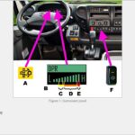
Image demonstrating how to properly probe a connector.
Decoding Ignition Waveforms: LH 2.2 vs. LH 2.4
Volvo used different ignition systems in these LH versions. LH 2.0, 2.1, and 2.2 use a distributor with a Hall-type position sensor, generating one pulse per cylinder. LH 2.4 utilizes a Bosch EZ116K ignition box with a VR-type sensor and a 60-2 toothed flywheel/flexplate for crankshaft position.
LH 2.2 Distributor Position Sensor
The Hall-type sensor generates a square wave pulse for each cylinder. Distributor rotation adjusts idle timing. Probe the center pin (“O”) of the distributor connector, typically a yellow wire.
(Waveform images for LH 2.2 are not available. A typical waveform would be a 0-10 volt square wave, two pulses per revolution, ~40% duty cycle. Idle frequency should be ~30Hz, and 2000 RPM should be ~70Hz.)
LH 2.4 Crankshaft Position Sensor (CPS)
The VR-type sensor generates voltage proportional to engine RPM. Low voltage can indicate sensor damage or incorrect distance from the flywheel/flexplate, leading to a no-start condition. Probe the center pin (2) of the CPS connector, usually a red-yellow wire.
Image of the Crankshaft Position Sensor connector.
Zoomed-out view of CPS waveform at idle.
Zoomed-in view of CPS waveform at idle, showing the missing tooth section.
CPS waveform at 2000 RPM.
Analyzing other Ignition Components
Powerstage
The powerstage amplifies the EZK box’s low-current spark signal to drive the ignition coil. Probe pin 5 (gray wire) of the powerstage connector.
Image of the Powerstage connector.
Powerstage waveform at idle.
Powerstage waveform at 2000 RPM.
Coil Primary and Secondary
Analyzing the coil primary voltage helps in basic diagnostics. Use a 10X probe to avoid scope damage. Probe the coil “-” tab (red-white wire). Secondary voltage requires a specialized high-voltage probe.
Image of the Coil Primary connector.
Coil Primary waveform at idle.
Coil Primary waveform at 2000 RPM.
Coil Primary single pulse waveform.
Coil Secondary waveform setup.
Using a cheap auto diagnostic tool like a scope, even a basic one, allows for a deeper understanding of your Volvo’s ignition system. These waveforms provide valuable insights into the health of various components, enabling you to diagnose issues effectively.