The Cummins 8.3 engine is a workhorse known for its reliability and power. Understanding its fuel system is crucial for maintenance and troubleshooting. This article provides a detailed overview of the Cummins 8.3 Fuel System Diagram, outlining the key components and fuel flow path.
Key Components of the Cummins 8.3 Fuel System
The Cummins 8.3 fuel system typically consists of these main components:
- Lift Pump: This pump, often located behind the ECU cooler, provides initial low-pressure fuel delivery to the engine. It runs for a short period upon key activation, priming the system. This is sometimes referred to as a “prime pump”.
- Gear Pump: This pump, housed within the same unit as the high-pressure pump, further increases fuel pressure after the lift pump. It moves fuel through the system and to the secondary filter.
- High-Pressure Pump: This pump, also located in the same housing as the gear pump, generates the extremely high pressure required for fuel injection in the common rail system. Pressure can reach up to 30,000 psi.
- Fuel Filter(s): The system incorporates primary and secondary fuel filters to remove contaminants and protect the sensitive injection components.
- Fuel Rail: The high-pressure fuel from the pump is delivered to the fuel rail, which distributes it to the individual fuel injectors.
- Fuel Injectors: These electronically controlled injectors precisely meter and atomize fuel into the combustion chambers.
- Fuel Return Line: Excess fuel from the injectors and rail is returned to the tank via the return line. This helps regulate fuel temperature and pressure.
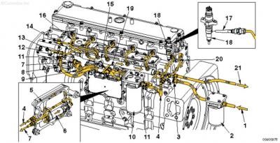 Common Rail Fuel System Diagram
Fuel Flow Path in the Cummins 8.3
The fuel flow generally follows this sequence:
- Fuel Tank: Fuel is drawn from the tank by the lift pump. The fuel tank also acts as a heat sump, dissipating heat from the returned fuel.
- Lift Pump: The lift pump provides initial low pressure to the gear pump. It operates for a short duration on key-on to prime the system.
- Gear Pump: The gear pump increases the fuel pressure and delivers it to the secondary fuel filter.
- Fuel Filter: Contaminants are removed from the fuel, ensuring clean fuel reaches the high-pressure pump.
- High-Pressure Pump: The fuel is pressurized to extremely high levels (around 30,000 psi) necessary for injection.
- Fuel Rail: High-pressure fuel is distributed to each injector via the fuel rail.
- Fuel Injectors: Injectors receive high-pressure fuel and precisely meter the correct amount into each cylinder for combustion.
- Fuel Return Line: Unused fuel is returned to the fuel tank, completing the cycle.
Importance of Fuel System Maintenance
Regular maintenance of the Cummins 8.3 fuel system is essential for optimal engine performance and longevity. This includes:
- Fuel Filter Replacement: Regularly replacing fuel filters ensures clean fuel and prevents damage to the injection system.
- Fuel Water Separator Draining: Removing accumulated water from the fuel water separator prevents corrosion and other issues.
- Checking for Leaks: Regularly inspect for fuel leaks, as even small leaks can indicate potential problems and lead to significant issues. High pressure leaks are especially dangerous.
- Monitoring Fuel Pressure: Ensuring correct fuel pressure is vital for proper engine operation. Low pressure can cause performance issues while high pressure can damage components.
Understanding the Cummins 8.3 fuel system diagram allows for effective troubleshooting and maintenance, contributing to the engine’s reliable operation.