The Dball2 connector plays a crucial role in various vehicle systems. This guide provides a detailed overview of the dball2 connector, including pinouts, wire diagrams, and common connection points. Whether you’re installing an aftermarket accessory or troubleshooting an electrical issue, understanding the dball2 wiring is essential.
Decoding the dball2 Connector
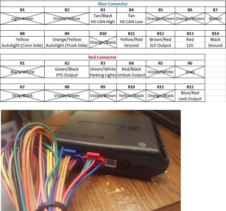
The dball2 connector typically houses multiple wires, each with a specific function. Identifying these wires is crucial for proper installation and operation. The following diagram illustrates a typical dball2 connector pinout, indicating which wires are commonly used and which can be removed if not required. Pins can be easily removed with a small precision flat-head screwdriver or needle. Apply downward and outward pressure where the wire enters the connector. Wire locations are labeled by connector color and pin number (e.g., B3 represents the blue connector, pin 3, or the Tan/Black wire for HS CAN High).
Navigating the Under-Dash Layout
The area under the dash can be a maze of wires and connectors. This labeled diagram provides a clear overview of the layout, simplifying the process of locating specific connection points. Each point is identified by a number combined with a pin number to specify the exact location (e.g., 2-16 indicates the PTS Output on the Smart Key ECU Assembly).
Essential Wire Pairings for dball2
Understanding the relationships between wire pairs is vital. This chart clearly outlines the common wire pairings found within the dball2 system, ensuring correct connections and functionality.
Key Connection Points: Smart Key, OBDII, and Main Body ECU
This section details the critical connection points related to the dball2 system.
Smart Key ECU Assembly
The Smart Key ECU Assembly plays a vital role in keyless entry and ignition systems. This image highlights the relevant connections on the Smart Key ECU, using clear labels for easy identification. Note the beige/tan connectors.
OBDII Connector
The OBDII connector is a standardized diagnostic port found in most modern vehicles. This labeled image clarifies the dball2 related connections within the OBDII port, simplifying the process of tapping into these wires for various applications. You may need to loosen the cable holder to gain more slack.
Main Body ECU Connector
The Main Body ECU (Electronic Control Unit) is a central control module responsible for managing various vehicle functions. This diagram illustrates the dball2 connections within the Main Body ECU connector.
By understanding the dball2 connector and its related connections, you can confidently tackle a wide range of automotive tasks, from installing aftermarket equipment to diagnosing electrical problems. Always refer to your vehicle’s specific wiring diagrams for accurate information.