Tracking your car’s location can be a valuable asset for security, monitoring teen drivers, or even just remembering where you parked in a বিশাল parking lot. This article will guide you through the process of programming a car GPS tracker using Arduino, a GSM module, and a GPS receiver. This project allows you to remotely receive your car’s GPS coordinates via SMS, providing a simple yet effective tracking solution.
Components You’ll Need
To build this car GPS tracker, you will need the following components:
- Arduino Board: An Arduino Uno or similar microcontroller board will serve as the brain of the tracker.
- Sim800L GSM/GPRS Module: This module enables your Arduino to communicate over the mobile network, sending SMS messages with GPS data.
- GPS Module (e.g., TinyGPS): This module will determine the car’s geographical coordinates.
- SoftwareSerial Library: This Arduino library allows serial communication on digital pins, necessary for communicating with the GSM and GPS modules.
- Relay Module (Optional): While not strictly for GPS programming, the original code includes relay control, which can be used for remote actions like disabling the engine.
- Connecting Wires and Breadboard: For prototyping and connecting the components.
- External Power Supply: To power the Arduino and modules in a car environment.
- SIM Card: A standard SIM card with SMS capability for the GSM module.
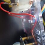
Wiring and Setup
Connect the components as follows:
- GSM Module (Sim800L):
- Sim800L RX pin to Arduino pin 7 (SoftwareSerial TX).
- Sim800L TX pin to Arduino pin 8 (SoftwareSerial RX).
- Power and Ground to appropriate Arduino pins or external power.
- GPS Module:
- GPS TX pin to Arduino pin 4 (SoftwareSerial RX for GPS).
- GPS RX pin to Arduino pin 5 (SoftwareSerial TX for GPS).
- Power and Ground to appropriate Arduino pins or external power.
- Relay Module (Optional):
- Relay control pin to Arduino pin 12.
- Relay power and ground as per module specifications.
- Pin 9 Connection: The original code uses pin 9 to control the GSM module’s power. Connect pin 9 to the power control pin of the Sim800L if needed for automatic power cycling.
Arduino Code Breakdown
Here’s a breakdown of the Arduino code and how it programs the GPS functionality:
#include <SoftwareSerial.h>
#include <TinyGPS.h>

SoftwareSerial Sim800L(7, 8); // RX, TX for GSM
int state = 0;
const int pin = 9; // GSM power control pin
float gpslat, gpslon; // Variables for latitude and longitude
TinyGPS gps; // GPS object
SoftwareSerial sgps(4, 5); // RX, TX for GPS

// Variable to store text message
String textMessage;

// Create a variable to store Engine state
String Engine = "HIGH";

// Relay connected to pin 12
const int relay = 12;

void setup() {
  // Automatically turn on the shield
  digitalWrite(9, HIGH);
  delay(1000);
  digitalWrite(9, LOW);
  delay(5000);

  // Set relay as OUTPUT
  pinMode(relay, OUTPUT);

  // By default the relay is off
  digitalWrite(relay, HIGH);

  // Initializing serial communication
  Serial.begin(9600); // For debugging via serial monitor
  Sim800L.begin(9600); // GSM module serial
  sgps.begin(9600);    // GPS module serial
}

void loop() {
  while (sgps.available()) { // Read data from GPS module
    int c = sgps.read();
    if (gps.encode(c)) { // Encode GPS data
      gps.f_get_position(&gpslat, &gpslon); // Get latitude and longitude
    }
  }
  if (digitalRead(pin) == HIGH && state == 0) { // Trigger SMS on pin HIGH
    Sim800L.print("r");
    delay(1000);
    Sim800L.print("AT+CMGF=1r"); // Set SMS mode
    delay(1000);
    Sim800L.print("AT+CMGS="""+xxxxxxxxxxxxxx""r"); // Replace with phone number
    delay(1000);
    Sim800L.print("Latitude :");
    Sim800L.println(gpslat, 6); // Send latitude
    Sim800L.print("Longitude:");
    Sim800L.println(gpslon, 6); // Send longitude
    delay(1000);
    Sim800L.write(0x1A); // End SMS command
    delay(1000);
    state = 1;
  }
  if (digitalRead(pin) == LOW) {
    state = 0;
  }

  // GSM module initialization and SMS command handling (for relay control - optional)
  delay(20000);
  Serial.print("SIM900 ready...");
  Sim800L.print("AT+CMGF=1r");
  delay(100);
  Sim800L.print("AT+CNMI=2,2,0,0,0r");
  delay(100);

  if (Sim800L.available() > 0) { // Check for incoming SMS
    textMessage = Sim800L.readString();
    Serial.print(textMessage);
    delay(10);

    if (textMessage.indexOf("ON") >= 0) { // Relay ON command
      digitalWrite(relay, LOW);
      Engine = "on";
      Serial.println("Relay set to ON");
      textMessage = "";
    }

    if (textMessage.indexOf("OFF") >= 0) { // Relay OFF command
      digitalWrite(relay, HIGH);
      Engine = "off";
      Serial.println("Relay set to OFF");
      textMessage = "";
    }

    if (textMessage.indexOf("STATE") >= 0) { // State request command
      String message = "Engine is " + Engine;
      sendSMS(message);
      Serial.println("Engine state request");
      textMessage = "";
    }
  }
}

// Function to send SMS
void sendSMS(String message) {
  Sim800L.print("AT+CMGF=1r");
  delay(100);
  Sim800L.println("AT + CMGS = ""+xxxxxxxxxxxxxx"""); // Replace with phone number
  delay(100);
  Sim800L.println(message); // SMS message content
  delay(100);
  Sim800L.println((char)26); // End SMS command (Ctrl+Z)
  delay(100);
  Sim800L.println();
  delay(5000);
}
Code Explanation:
- Includes Libraries:
SoftwareSerial.hfor serial communication with GSM and GPS, andTinyGPS.hto parse GPS data. - SoftwareSerial Instances:
Sim800L(7, 8)andsgps(4, 5)define software serial ports for the GSM and GPS modules respectively. - GPS Data Handling: The
loop()function continuously reads data from the GPS module usingsgps.available()andsgps.read(). Thegps.encode(c)function parses the incoming GPS NMEA sentences.gps.f_get_position(&gpslat, &gpslon)extracts the latitude and longitude. - SMS Sending: When
digitalRead(pin)is HIGH (you can trigger this with a button or sensor), the code sends an SMS with the current GPS latitude and longitude to a predefined phone number. Remember to replacexxxxxxxxxxxxxxwith your actual phone number including the country code. - Relay Control (Optional): The code also includes functionality to control a relay via SMS commands “ON”, “OFF”, and “STATE”. This is an optional feature for remote control, not directly related to GPS programming but included in the original example.
Programming and Testing
- Upload the Code: Copy the code to your Arduino IDE, replace the placeholder phone number, and upload it to your Arduino board.
- Insert SIM Card: Insert an active SIM card into the Sim800L module.
- Power Up: Power the Arduino and the connected modules. Ensure the GSM module registers on the network (check the module’s indicator LED).
- Trigger GPS Reading and SMS: Trigger the digital input pin (pin 9 in the code, if used) to HIGH. The Arduino should then acquire GPS coordinates and send an SMS to your phone with the location data.
- Verify Location: Check the SMS on your phone. It should contain the latitude and longitude coordinates. You can use online map services to verify the location.
Enhancements and Further Development
- Real-time Tracking: Instead of sending location only when triggered, modify the code to send GPS location at regular intervals for continuous tracking.
- Data Logging: Store GPS data on an SD card for historical tracking.
- Web/App Integration: Use GPRS capabilities of the Sim800L to send GPS data to a web server or mobile app for real-time map visualization.
- Geofencing: Implement geofencing features to receive alerts when the car enters or exits predefined areas.
- Power Optimization: Optimize the code and hardware for low power consumption, suitable for battery-powered car tracking applications.
This project provides a foundation for building a functional car GPS tracker. By understanding the code and hardware, you can customize and expand its capabilities to meet your specific tracking needs.