Are you the proud owner of a Japanese import vehicle, but find yourself frustrated because the car radio struggles to pick up local FM stations clearly? You’re not alone. Japanese car radios operate on a different FM broadcast band (76-90 MHz) compared to most of the world, which uses the 87.5 to 108 MHz CCIR band. While band expanders exist, they often compromise audio quality and don’t accurately display the tuned frequency.
This comprehensive guide provides a detailed walkthrough on how to modify your Japanese car radio to natively tune across the standard CCIR band. This is a hands-on project that delves into the electronics of your car stereo, offering a rewarding solution for true audio enthusiasts. Please note that this guide is continually being refined, and updates with more detailed photos and information will be added periodically.
Understanding the Basics
Before we dive into the modification process, it’s important to understand a few key points.
Firstly, not all car radios are suitable for this type of conversion. This guide is generally more applicable to Original Equipment Manufacturer (OEM) radios, which are factory-installed units. Aftermarket radios designed specifically for the Japanese market may have different internal architectures that make conversion more complex or impossible.
OEM car radios are often designed with a global market in mind. Manufacturers frequently utilize a base design and then adapt it slightly for specific regional markets. This modular design approach is what makes it possible to modify certain Japanese radios to work with worldwide FM frequencies.
Essential Tools and Materials
To successfully modify your Japanese car radio, you’ll need to gather the following tools and materials. Having the right equipment is crucial for a smooth and successful conversion.
Must-Have Items
- Fine-tipped Temperature Controlled Soldering Iron: Precision soldering is essential for working with the delicate components inside a car radio. Temperature control is important to avoid overheating and damaging components.
- Fine Solder: Use high-quality, fine solder for creating clean and reliable connections.
- Desoldering Wick: This braided copper wick is used to remove excess solder, allowing you to cleanly remove components.
- Fine Enamelled Copper Wire: Thin, insulated copper wire is needed for making jumper connections and modifications on the circuit board.
- Volt Meter (Multimeter): A multimeter is indispensable for testing voltages, continuity, and resistance, helping you diagnose and verify your modifications.
- Capacitance Tester: While not strictly essential, a capacitance tester can be very helpful for identifying and measuring capacitor values, especially varicaps.
- Phillips #0 Screwdriver (and other types as necessary): Car radios are held together with various types of screws. A Phillips #0 screwdriver is a common size, but having a set of precision screwdrivers in different sizes and types (like flat-head, Torx) is recommended.
- Working FM Radio (Monitor Radio): A standard FM radio is needed to monitor and compare frequencies as you adjust your Japanese car radio.
- 12-14v DC Power Supply (1.5A minimum): You’ll need a stable DC power supply to power the car radio on your workbench for testing and modification. A 1.5A minimum rating should be sufficient.
- Suitable Plug and Harness to Connect to the Radio: To power the radio and connect speakers, you’ll need the correct wiring harness or plug that mates with the radio’s connector.
- 4-8 ohm Speaker: A standard car speaker (4 or 8 ohms) is needed to hear audio output from the radio during testing.
- FM or VHF Antenna (or a long scrap of wire): An antenna is necessary to receive FM signals. You can use a proper FM antenna or a simple length of wire as a temporary antenna.
Recommended Items
- Tinned Copper Wire: Stranded tinned copper wire is useful for making more robust connections compared to enamelled wire, especially for power and speaker connections.
- Ceramic or Plastic Tuning Coil Adjustment Tool: These non-metallic tools are designed for adjusting the ferrite slugs in tuning coils without affecting their inductance or damaging them.
Advanced Tools (Optional)
- Oscilloscope: An oscilloscope is a powerful tool for visualizing electronic signals. While not essential for this modification, it can be incredibly helpful for diagnosing more complex issues or for advanced troubleshooting.
Step-by-Step Modification Method
Now, let’s get into the detailed steps for modifying your Japanese car radio. This process involves carefully disassembling the radio, identifying key components, and making precise adjustments.
1. Removing the Stereo from Your Car
The first step is to safely remove the car radio from your vehicle’s dashboard. This process varies depending on the car model and radio type.
- Consult Your Car’s Manual or Online Resources: The best resource is your car’s owner’s manual, which often provides instructions on radio removal. You can also search online forums and websites dedicated to your car model. Enthusiast forums are goldmines of information, with many users sharing step-by-step guides and videos.
- Use Trim Removal Tools: Automotive trim removal tools (plastic pry tools) are highly recommended to avoid damaging your dashboard trim.
- Disconnect the Battery (Optional but Recommended): While not always strictly necessary for simply removing the radio, disconnecting the car battery can add an extra layer of safety and prevent accidental shorts.
- Carefully Disconnect Wiring Harnesses: Once the radio is loose, carefully disconnect all wiring harnesses and antenna cables from the back of the unit. Remember to note or photograph the connections for easy reinstallation later.
- Seek Professional Help if Unsure: If you’re uncomfortable with any part of this process, don’t hesitate to seek assistance from a local car audio shop.
2. Disassembling the Radio
With the radio removed from your car, the next step is to carefully open it up to access the internal circuitry.
- Work in a Clean and Well-Lit Area: A clean workspace will prevent dust and debris from contaminating the radio’s internals. Good lighting is essential for seeing the small components clearly.
- Start with the Top or Side Panels: Most car radios are designed to be disassembled in a specific order. Often, you’ll start by removing screws from the top or side panels.
- Proceed to the Front Panel: After removing the initial panels, carefully work your way to the front panel. Look for screws hidden behind knobs or trim pieces.
- Take Photos as You Go: This is crucial! As you disassemble the radio, take pictures of each step, especially screw locations and cable connections. This photographic record will be invaluable when you reassemble the radio.
- Note Screw Types and Locations: Keep track of different screw types and their locations. You can use small containers or labeled bags to organize screws from different sections.
- Handle Components with Care: Be gentle when handling internal components, especially circuit boards and ribbon cables. Avoid static electricity by grounding yourself or using an anti-static wrist strap.
3. Navigating the Internal Circuitry
Once the radio is open, you need to identify the key components on the circuit board, particularly the tuner module and the microprocessor.
Identifying Major Components
- Microprocessor: This is the brain of the radio, controlling its functions. It’s usually the largest chip with the most pins. Look for part numbers on the chip and search online (Google) for datasheets to confirm its identity.
- Audio Processing Chip: This chip handles audio signal processing, like volume control, equalization, and audio output.
- PLL (Phase-Locked Loop) for Tuner: The PLL circuit is crucial for frequency synthesis in the tuner. It generates the local oscillator frequencies needed for tuning.
- CD Mechanism ICs (if applicable): If your radio has a CD player, you’ll see ICs that control the CD mechanism.
- Tuner Module: The tuner module is usually a shielded, self-contained unit soldered to the main PCB. It’s responsible for receiving and demodulating FM and AM radio signals.
Locating Key Pins on the Tuner Module
- VT (Tuning Voltage) Pin: Most tuners are voltage-tuned. The frequency is adjusted by varying the voltage on the VT pin. This pin typically ranges from ground (lowest frequency) to 8-9V (highest frequency). Look for markings like “VT” or “Tune” near the tuner module pins. If not labeled, you can identify it by measuring voltage changes while tuning the radio (before modification). Mark this pin carefully.
- Vcc (Voltage Common Collector) Pin: This is the power supply pin for the tuner module. It usually receives a constant voltage of 8-9V. If not clearly marked, look for a pin with a stable 8-9V reading.
4. Setting the Area/Region
Many OEM radios have internal settings that determine the operating region (e.g., Japan, North America, Europe). These settings are often configured using jumpers, resistors, or diodes near the microprocessor.
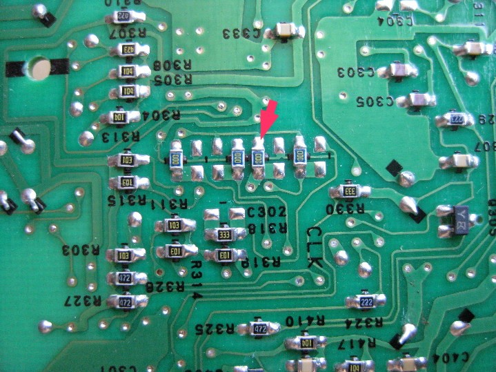
- Locate Area Jumpers/Resistors/Diodes: Look around the microprocessor for groups of small components like 0-ohm resistors or jumper links. Some older radios might use diodes. These components are often located near unpopulated solder pads. You might even find markings like “Area 1” and “Area 2” on the PCB.
- Area Designations: “Area 1” often corresponds to North America, while “Area 2” may suit most other regions outside Japan.
- Document the Original Jumper Configuration: Before making any changes, carefully photograph or draw a diagram of the original jumper layout. This is essential for reverting back to the original configuration if needed.
Alt text: Close-up showing the original jumper configuration on a car radio circuit board, highlighting the area selection jumpers before modification.
- Experiment with Jumper Settings (One at a Time): Using your soldering iron and desoldering wick, carefully remove one jumper resistor at a time. Then, move it to a corresponding set of unpopulated solder pads nearby.
- Test After Each Jumper Change: Power on the radio (using your DC power supply, speaker, and antenna) after each jumper modification to see if the FM frequency display changes. Look for a change from 76 MHz to 87.5 MHz as the starting frequency.
- Check AM and FM Tuning Steps: If changing a jumper has an effect, also check if the AM tuning steps are correct for your region (9 kHz or 10 kHz). Incorrect AM steps might indicate incorrect FM band stepping as well.
- Return Jumpers to Original Position if No Effect: If a jumper change doesn’t produce a noticeable effect, immediately move it back to its original location and try another jumper.
- Caution: Avoid Short Circuits: Be extremely careful not to accidentally short the 5V power rail to ground while moving jumpers, as this could permanently damage the radio.
Success with Area Jumper?
- If Successful: If you find the correct area jumper, the radio might now display 87.5 MHz instead of 76 MHz when powered on. Connect an antenna and speaker. Tune to a local FM station and see if it works. If the radio now tunes correctly and receives local stations, you’re in luck! Proceed to the “Testing and Adjusting” section later in this guide.
- If Unsuccessful: If the area jumper modification doesn’t enable proper tuning to local stations, you’ll need to proceed to the next step: “Hacking the Tuner.”
5. Hacking the Tuner Module
If the area jumper modification alone wasn’t sufficient, you’ll need to directly modify the tuner module itself. This usually involves adjusting or replacing components within the tuner to shift its frequency range.
Understanding Tuner Basics
To understand the tuner modifications, a basic understanding of FM tuner operation is helpful. Car radios typically use a superheterodyne receiver architecture. We’ll focus on the front-end of the tuner, which includes:
- RF Amplifier: Amplifies the weak radio signals received by the antenna.
- Local Oscillator: Generates a signal that mixes with the incoming RF signal to create an intermediate frequency (IF).
- Mixer: Combines the RF signal and local oscillator signal to produce the IF signal.
- Filter: Selects the desired IF signal and rejects unwanted frequencies.
The tuning of the tuner is achieved through tuned circuits, which are typically LC circuits (inductor-capacitor circuits).
Alt text: Schematic diagram of a typical automotive FM tuner front-end circuit based on the LA1175M IC, illustrating the RF amplifier, local oscillator, mixer, and tuned circuits.
In these tuned circuits, varicap diodes (also known as varactors or variable capacitance diodes) are used as voltage-controlled variable capacitors. By changing the voltage applied to the varicaps (VT), we change their capacitance, which in turn changes the resonant frequency of the tuned circuits and thus the tuning frequency of the radio.
We have two primary methods for adjusting the tuner’s frequency range:
- Adjusting the Inductance of Coils: Changing the inductance of the coils in the tuned circuits will shift the frequency range.
- Replacing Varicap Diodes: Replacing the varicaps with types that have a different capacitance range can also shift the tuning range.
Adjusting the coils is usually easier to attempt first, so we’ll start with that.
Identifying the FM Section and Marking Coils
- Locate FM and AM Sections: Tuner modules often have separate sections for FM and AM. In many designs, these sections are physically located at opposite ends of the tuner PCB.
- Identify FM Section using IC Part Numbers: The quickest way to identify the FM section is to look up the part numbers of the ICs on the tuner module using Google. Datasheets or application notes for these ICs will usually indicate whether they are for FM or AM.
- Mark Coil Positions: Use a fine permanent marker to carefully mark the current position of the ferrite slug (if present) in each adjustable coil in the FM section. This will serve as a reference point if you need to revert to the original settings.
Overriding the PLL and Manual Tuning
After attempting the microprocessor jumper modification, the radio’s PLL (Phase-Locked Loop) might be trying to tune within the Japanese band (76-90 MHz), even if the display shows a different frequency. This can cause the VT (tuning voltage) pin to be stuck at its maximum voltage (8-9V). To bypass this, we’ll temporarily override the PLL and manually control the tuning voltage.
- Disconnect the VT Pin: Carefully desolder or cut the connection to the VT pin of the tuner module.
- Connect a Potentiometer (Pot) for Manual Tuning: Wire a 50k linear potentiometer (B-type) as a voltage divider. Connect the wiper (center pin) of the pot to the VT pin on the tuner module. Connect one end of the pot to ground and the other end to the tuner’s Vcc (8-9V) supply.
Alt text: Wiring diagram showing how to connect a potentiometer to the VT pin of the tuner module to manually control the tuning voltage, bypassing the radio’s PLL.
- Manually Tune with the Pot: Now you can use the potentiometer to manually sweep the tuning voltage across the tuner’s entire range. Rotate the pot and listen for radio stations. You should hopefully be able to pick up local stations, especially at the lower end of the tuning range (lower pot resistance).
Locating and Adjusting the Oscillator Coil
The oscillator coil is a key component in setting the tuner’s frequency range. Adjusting this coil is often the most effective way to shift the tuning band.
- Tune Monitor Radio to a Mid-Band Station: Tune your working monitor FM radio to a local station in the middle of the FM band (e.g., 96-100 MHz).
- Set Manual Tuning Pot to Mid-Range: Adjust the potentiometer connected to your car radio’s tuner to approximately the middle of its range.
- Identify Oscillator Coil by Proximity: Carefully move your finger (or a non-metallic tool) near each coil in the FM tuner section, one at a time. When you touch or get close to the oscillator coil, you should hear the same station from your monitor radio start to come in (or change significantly) on your car radio. This is because your finger is slightly detuning the oscillator circuit.
- Adjust Oscillator Coil: Once you’ve identified the oscillator coil, carefully adjust it.
- Ferrite Core Coils: If the coil has a ferrite slug (adjustable core), use a ceramic or plastic tuning tool to gently turn the slug. Small adjustments can make a significant difference.
- Air Core Coils: If the coil is air-cored (no ferrite slug), you might need to carefully adjust the spacing between the coil windings. Gently spread or compress the windings. For coils wound on plastic formers, you might need to desolder the coil and remove a small number of turns.
Alt text: Close-up photo of a tuner coil, highlighting its construction and adjustable ferrite slug, used for fine-tuning the oscillator frequency in car radios.
- Iterative Adjustment and Testing: Adjust the oscillator coil in small increments and check your tuning range using the potentiometer. The goal is to shift the tuning range so that it covers the standard 87.5-108 MHz CCIR band. You might need to iterate through adjustments multiple times to get it right.
- Reconnecting VT Pin and Testing Radio Controls: Once you are able to tune across the local band using the potentiometer, remove the potentiometer, reconnect the original VT pin, and test if the radio now tunes correctly using its own controls. Check if it tunes across the entire desired band (some radios might still only tune a limited bandwidth, like 16 MHz).
Replacing Varicap Diodes (If Necessary)
If adjusting the oscillator coil doesn’t provide sufficient tuning range, you might need to replace the varicap diodes in the tuner. This is a more complex step and is often a trial-and-error process.
- Identify Varicap Diodes: Look on the underside of the tuner PCB for small, three-legged surface-mount components. Varicaps are typically connected across a coil with two of their legs, and the third leg is connected (often via a resistor) to the VT pin. You might find two to four varicaps in the FM tuner section.
Alt text: Underside view of a tuner PCB showing identified varicap diodes, surface-mount components with three legs, crucial for voltage-controlled tuning in FM radios.
- Determine Varicap Type (Difficult): It’s often challenging to determine the exact type of varicaps originally used without datasheets or service manuals.
- Consider SVC203 Varicaps as a Starting Point: For Sanyo tuner ICs (and some Clarion tuners like the 80-8028A), SVC203 varicaps have been reported to work well as replacements. However, the ideal replacement type can vary widely depending on the tuner design.
- Measure Original Varicap Capacitance (Optional): If possible, carefully remove one of the original varicaps and try to measure its capacitance range using a capacitance meter. This might give you a clue about the required capacitance range for replacement varicaps.
- Replace All Varicaps Simultaneously: When replacing varicaps, it’s essential to replace all of them in the FM tuner section with identical new types to maintain balanced tuning characteristics.
- Trial and Error: Varicap replacement is often a process of trial and error. You might need to experiment with different varicap types to find ones that provide the desired tuning range. Patience is key!
- Temporary Soldering for Testing: If you have removed the tuner module from the main PCB for easier access, temporarily solder it back to the underside of the PCB for testing during varicap replacement experiments.
6. Testing and Fine-Tuning
Once you’ve made modifications, it’s crucial to thoroughly test and fine-tune the radio.
- Reassemble Partially for Testing: You might be able to test the radio with just the main PCB and tuner module connected, without fully reassembling everything (depending on the radio model). Some radios (like Clarion and Sony) might work without the CD or tape decks connected for testing the radio function. However, some (like certain Alpine models) might require the CD mechanism to be connected for audio output from the radio.
- Check for Basic Functionality: Power on the radio and check if it powers up and displays frequencies.
- Verify Connections and Solder Bridges: If the radio doesn’t work at all, double-check all your connections and modifications. Look for accidental solder bridges (shorts) between pins or traces. Ensure you haven’t missed reconnecting any cables.
- Antenna Connection is Essential: Remember that car tuners usually require an antenna to receive signals. Make sure your antenna (or a wire acting as an antenna) is properly connected.
- Band Scan and Station Reception: Tune across the entire FM band and compare the stations received with your monitor radio. Verify that all local stations are being picked up clearly.
- Scanning/Seeking Function: Test the radio’s scanning or seeking function. If it doesn’t work correctly, you might need to make further adjustments to the tuner, possibly another coil (related to tracking or IF alignment).
- Fine-tune Oscillator Coil (Again): If needed, you can make further微调 (fine adjustments) to the oscillator coil to optimize reception and band coverage.
Successful Conversion Examples
Here are some car radio models that have been successfully converted using methods similar to those described in this guide. More detailed instructions for specific models might be added in future updates.
- Clarion 80-8028A Tuner Module: Often found in various Japanese car models. SVC203 varicaps have been used successfully in conversions of this tuner module.
- Sony Car Radios: Many Sony OEM car radios have been reported to be convertible using area jumper modifications and/or tuner adjustments.
This guide provides a comprehensive approach to converting your Japanese car radio to tune to worldwide FM frequencies. Remember to proceed with caution, take your time, and enjoy the satisfaction of successfully modifying your car audio system!