For many tech enthusiasts, the worlds of software and hardware often seem miles apart. We spend countless hours coding, yet the physical devices that bring our digital creations to life can feel like a mystery. Electronics, in particular, is often perceived as a complex domain, requiring years of engineering expertise to even begin to understand. However, this couldn’t be further from the truth, especially with user-friendly platforms like Arduino.
As a car enthusiast and coding hobbyist myself, I’ve always been fascinated by the idea of bridging the gap between software and the physical world. Remote Control (RC) cars were a childhood passion, and revisiting that passion as an adult, now armed with coding skills and an Arduino kit, seemed like the perfect project. This guide is born from that very journey – a desire to demystify electronics and programming by building something fun and tangible: an Arduino-controlled RC car.
This tutorial is designed for absolute beginners. You don’t need prior experience in programming, Arduino, or electronics. While some background in these areas might be helpful, the steps are laid out clearly and comprehensively, ensuring anyone can follow along and successfully build their own Bluetooth-controlled RC car. We’ll take a practical, hands-on approach, focusing on readily available materials and providing detailed code explanations. The beauty of this project lies in its adaptability. The principles and techniques you learn here can be applied to a wide range of other exciting DIY electronics projects. So, let’s dive in and bring a classic toy into the 21st century!
One of the key choices in this project is using a power bank as the power source. In today’s world, power banks are incredibly accessible and often more economical than traditional batteries. Many of us already own them, and they offer the benefits of being reusable and rechargeable, making this a sustainable and cost-effective approach.
Let’s get started on building your own programmable RC car!
Step 1: Assembling the RC Car Chassis
The first step is to assemble the foundation of our project – the RC car chassis. If you purchased a chassis kit, it likely includes assembly instructions. However, to ensure everyone is on the same page, here’s a step-by-step guide:
-
Prepare the Components: Gather the main chassis frame, motor mounting brackets (usually four small plastic pieces, two for each motor), screws, brass spacers, nuts, the DC motors, a spare USB cable, and jumper wires (male-male and female-male).
-
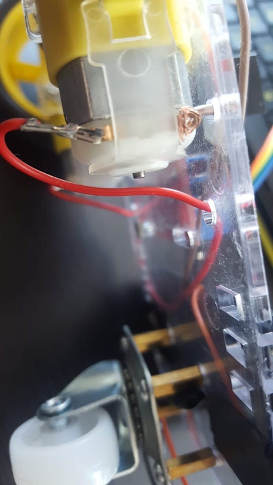
Connect Wires to Motors: Each DC motor needs to be connected to power. Attach a wire to each terminal (pin) of both motors. Soldering provides the most reliable connection, but if you don’t have a soldering iron, you can securely twist or “knot” the wires to the pins. Ensure a firm connection for reliable power delivery.
-
Prepare the USB Cable for Power: Take an old USB cable that you no longer need. Cut off one end, leaving about 20cm (8 inches) of cable length.
-
Expose Power Wires: Carefully strip a few centimeters of the outer insulation of the USB cable to reveal the internal wires. You should find several wires inside, typically including red (positive – 5V) and black (ground – GND). Identify and strip 2-4 cm of insulation from both the red and black wires. For a more robust connection, you can reinforce these connections by twisting them with longer jumper wires or soldering them. This ensures a reliable power supply to the motor controller.
Image: A USB cable stripped to show the red and black power wires, prepared for use in the RC car’s power circuit.
-
Mount Motors to Chassis: Attach the DC motors to the chassis frame using the plastic brackets, screws, and nuts. Most chassis kits are designed with specific motor orientations in mind. Typically, each motor has a small dot or marking on one side. Ensure these dots face inwards, towards each other, when both motors are mounted. This is important for consistent motor direction.
-
Install Supporting Wheel: Locate the set of four small holes, usually in a square pattern, at the rear end of the chassis frame. These are for the supporting nylon wheel, which provides stability. Attach the brass spacers to these holes using screws, ensuring the spacers are on the same side of the frame as the motors.
-
Mount Nylon Wheel: Attach the nylon supporting wheel to the brass spacers using screws. This wheel will act as a caster, allowing for smooth turns.
-
Attach Wheels to Motors: Push the wheels onto the motor shafts. Note the shape inside the wheel hub; it’s designed to fit snugly onto the motor shaft. You might encounter some resistance, but apply firm, gentle pressure to securely attach the wheels.
-
Mount Arduino and Motor Controller: Position the Arduino UNO board and the L298N DC motor controller onto the chassis frame. Use the remaining screws and nuts from the kit to secure them. Electrical insulation tape can be used to manage wires and prevent shorts, ensuring a tidy and safe assembly.
Step 2: Wiring the Electronics
With the chassis assembled and components mounted, it’s time to connect the electronics. Prepare male-male and female-male jumper wires for this stage.
-
Connect Motors to Motor Controller: Connect the wires coming from the DC motors to the L298N DC motor controller. The L298N has output terminals labeled OUT1, OUT2, OUT3, and OUT4. For each motor, connect one wire to a ‘minus’ (-) terminal and the other to a ‘plus’ (+) terminal. A common wiring configuration is:
- OUT1: Left Motor (-) GND cable
- OUT2: Left Motor (+) cable
- OUT3: Right Motor (+) cable
- OUT4: Right Motor (-) GND cable
-
Connect Arduino to Motor Controller (Control Signals): Now, we need to send control signals from the Arduino to the motor controller. Use jumper wires to connect the Arduino digital pins to the L298N input pins (IN1, IN2, IN3, IN4):
- L298N IN1: Arduino Digital Pin 5
- L298N IN2: Arduino Digital Pin 6
- L298N IN3: Arduino Digital Pin 10
- L298N IN4: Arduino Digital Pin 11
Female-male jumper wires are ideal for this connection. If you only have male-male jumpers, you might need to modify them or use a bit of wire to bridge the connection.
-
Connect Bluetooth Module: The Bluetooth module (HC-06 or HC-05) allows wireless control of the RC car from your Android phone. Bluetooth modules typically have four pins: VCC, GND, TXD, and RXD. Connect them to the Arduino as follows:
- Bluetooth VCC: Arduino 5V
- Bluetooth GND: Arduino GND
- Bluetooth TXD: Arduino Digital Pin 0 (RXD)
- Bluetooth RXD: Arduino Digital Pin 1 (TXD)
Notice that the TXD (transmit data) pin of the Bluetooth module connects to the RXD (receive data) pin of the Arduino, and vice-versa. This is because the TX pin sends data, and the RX pin receives it.
-
Connect Piezo Buzzer (Optional Sound Effects): A piezo buzzer adds fun sound effects to your RC car. It has two legs: a longer leg (Anode +) and a shorter leg (Cathode -). Connect them as follows:
- Piezo Anode (+, longer leg): Arduino Digital Pin 3
- Piezo Cathode (-, shorter leg): Arduino GND
While a 330 Ohm resistor is often recommended between the piezo buzzer and the Anode pin to limit current, it’s optional for this project. Without a resistor, the buzzer might be louder.
-
Powering the Circuit: Use the USB cable you prepared earlier to power the motor controller. Connect the red wire (+) and black wire (-) to the L298N motor controller’s power input terminals:
- USB Red Wire (+): L298N 12V (or VMS – Motor Supply Voltage)
- USB Black Wire (-): L298N GND
-
Connect to Power Bank: Finally, connect two USB cables to your power bank. One cable will power the Arduino, and the other will power the DC motor controller via the USB cable you just connected. Mount the power bank to the chassis using electrical tape or another secure method. Some power banks have a power button, so ensure it’s switched on to power the circuit.
Step 3: Programming Your RC Car with Arduino IDE
With the hardware assembled and wired, the exciting part begins – programming the Arduino to control your RC car! You’ll need to download and install the Arduino IDE (Integrated Development Environment) from the official Arduino website (https://www.arduino.cc/). The Arduino IDE is the software we use to write, compile, and upload code to the Arduino board.
-
Configure Arduino IDE: Open the Arduino IDE. Go to Tools > Board and select Arduino Uno (or whichever Arduino board you are using). Then, go to Tools > Port. Connect your Arduino board to your computer using a USB cable. The Port menu should now show available serial ports. Select the port that corresponds to your Arduino (it might be labeled as COM followed by a number on Windows, or /dev/ttyACM or /dev/ttyUSB on Linux/macOS). If you’re unsure, try different ports until the upload works.
-
Upload the Arduino Code: You have two options for getting the code onto your Arduino:
- Option 1: Download and Open Code File: You can download the provided Arduino code file (if available – in this case, it’s embedded below). Open the downloaded file directly in the Arduino IDE.
- Option 2: Copy and Paste Code: Alternatively, you can copy the code provided below and paste it into a new Arduino IDE sketch (File > New).
-
Important: Disconnect Bluetooth Module for Upload: Before uploading the code, disconnect the jumper wires connected to Arduino Digital Pin 0 (RX) and Digital Pin 1 (TX) from the Bluetooth module. These pins are used for serial communication, and leaving the Bluetooth module connected can interfere with the code upload process. You can reconnect them after the code is successfully uploaded.
-
Upload the Code: Click the “Upload” button in the Arduino IDE (it’s usually a right-arrow icon). The IDE will compile your code and upload it to the Arduino board. You should see a “Done uploading” message in the IDE status bar once the process is complete.
-
Reconnect Bluetooth Module: After successful code upload, reconnect the Bluetooth module wires to Arduino Digital Pin 0 (RX) and Digital Pin 1 (TX). Also, reconnect the USB cable from the Arduino to your power bank to power up the RC car.
-
Download and Install Android App: To control your RC car via Bluetooth, you’ll need a compatible Android application. You can use the “ArduCar – Arduino RC Car Bluetooth Controller” app available on the Google Play Store. Search for it in the Play Store or use this link: . Install the app on your Android smartphone. You can also explore other similar apps that send compatible serial commands or even develop your own custom control app.
-
Control Your RC Car! Open the ArduCar app on your phone, connect to your Bluetooth module (you might need to pair your phone with the Bluetooth module first – often the default pairing code is 1234 or 0000). Use the app’s controls to drive your newly programmed RC car!
Here is the Arduino code to copy and paste into your Arduino IDE:
 #define in1 5
#define in2 6
#define in3 10
#define in4 11
int state;
int piezo = 3;

void setup() {
  pinMode(in1, OUTPUT);
  pinMode(in2, OUTPUT);
  pinMode(in3, OUTPUT);
  pinMode(in4, OUTPUT);
  pinMode(piezo,OUTPUT);
  Serial.begin(9600);
}

void loop() {
  if (Serial.available() > 0) {
    state = Serial.read();
    Stop();
    switch (state) {
      case 'F': forward(); soundFX(3000.0,30+400*(1+sin(millis()/5000))); break;
      case 'G': forwardleft(); soundFX(3000.0,60); break;
      case 'D': forwardright(); soundFX(3000.0,60); break;
      case 'N': backright(); soundFX(3000.0,30+100*(1+sin(millis()/2500))); break;
      case 'C': backleft(); soundFX(3000.0,30+100*(1+sin(millis()/2500)));
                 soundFX(3000.0,30+100*(1+sin(millis()/2500)));
                 soundFX(3000.0,30+100*(1+sin(millis()/2500)));
                 soundFX(3000.0,30+100*(1+sin(millis()/2500))); break;
      case 'B': back(); soundFX(3000.0,30+200*(1+sin(millis()/2500)));
                 soundFX(3000.0,30+200*(1+sin(millis()/2500)));
                 soundFX(3000.0,30+200*(1+sin(millis()/2500)));
                 soundFX(3000.0,30+200*(1+sin(millis()/2500))); break;
      case 'L': left(); soundFX(3000.0,60);
                 soundFX(3000.0,60);
                 soundFX(3000.0,60);
                 soundFX(3000.0,60); break;
      case 'R': right(); soundFX(3000.0,60);
                 soundFX(3000.0,60);
                 soundFX(3000.0,60);
                 soundFX(3000.0,60); break;
      case 'H': soundFX(3000.0,30+200*(1+sin(millis()/2500)));
                 soundFX(3000.0,60);
                 soundFX(3000.0,30+200*(1+sin(millis()/2500)));
                 soundFX(3000.0,60);
    }
  }
}

void forward() {
  analogWrite(in1, 255);
  analogWrite(in3, 255);
}

void forwardleft() {
  analogWrite(in1, 50);
  analogWrite(in3, 255);
}

void forwardright() {
  analogWrite(in1, 255);
  analogWrite(in3, 50);
}

void back() {
  analogWrite(in2, 255);
  analogWrite(in4, 255);
}

void backright() {
  analogWrite(in2, 50);
  analogWrite(in4, 255);
}

void backleft() {
  analogWrite(in2, 255);
  analogWrite(in4, 50);
}

void left() {
  analogWrite(in4, 255);
  analogWrite(in1, 255);
}

void right() {
  analogWrite(in3, 255);
  analogWrite(in2, 255);
}

void Stop() {
  analogWrite(in1, 0);
  analogWrite(in2, 0);
  analogWrite(in3, 0);
  analogWrite(in4, 0);
}

void soundFX(float amplitude,float period){
  int uDelay=2+amplitude+amplitude*sin(millis()/period);
  for(int i=0;i<200;i++){
    digitalWrite(piezo, HIGH);
    delayMicroseconds(uDelay);
    digitalWrite(piezo, LOW);
    delayMicroseconds(uDelay);
  }
}
Step 4: Understanding the Arduino Code and Bluetooth Configuration (Optional)
For those eager to understand how the code works, here’s a breakdown of the Arduino sketch. Arduino code is based on a simplified version of C/C++, making it relatively accessible even for beginners. Every Arduino program has two essential functions: setup() and loop().
1. void setup() { } – Initialization:
The setup() function runs only once when the Arduino board starts. It’s used to configure the pins and initialize settings.
void setup() {
  pinMode(in1, OUTPUT);
  pinMode(in2, OUTPUT);
  pinMode(in3, OUTPUT);
  pinMode(in4, OUTPUT);
  pinMode(piezo,OUTPUT);
  Serial.begin(9600);
}
pinMode(in1, OUTPUT);and similar lines: These lines set the specified Arduino pins (in1, in2, in3, in4, piezo) as OUTPUT. This means the Arduino will send signals out from these pins to control other components (like the motor controller and buzzer).Serial.begin(9600);: This initializes serial communication at a baud rate of 9600 bits per second. Serial communication is used to exchange data between the Arduino and other devices, in our case, the Bluetooth module. 9600 is a common and reliable baud rate for Bluetooth communication.
2. void loop() { } – Main Program Loop:
The loop() function runs continuously after the setup() function completes. This is where the main program logic resides, constantly checking for inputs and controlling the RC car.
void loop() {
  if (Serial.available() > 0) {
    state = Serial.read();
    Stop();
    switch (state) {
      // ... (case statements for different commands) ...
    }
  }
}
if (Serial.available() > 0): This checks if there is any data available to be read from the serial port (i.e., from the Bluetooth module).state = Serial.read();: If data is available, this line reads the incoming byte (character) from the serial port and stores it in thestatevariable. This character represents the command sent from your Android app (like ‘F’ for forward, ‘L’ for left, etc.).Stop();: Before executing any movement command, theStop()function is called to ensure the car stops before performing the new action. This prevents jerky movements.switch (state) { ... }: This is aswitchstatement that checks the value of thestatevariable and executes different actions based on the received command.
3. Command Cases (Inside the switch statement):
Each case corresponds to a different command character sent from the Android app.
case 'F': forward(); soundFX(3000.0,30+400*(1+sin(millis()/5000))); break;: If the received character is ‘F’, theforward()function is called to move the car forward, and thesoundFX()function is called to play a sound effect.break;exits theswitchstatement after executing the corresponding case.- Similar
casestatements exist for other commands like ‘G’ (forward-left), ‘D’ (forward-right), ‘B’ (backward), ‘L’ (left), ‘R’ (right), ‘H’ (horn/special sound), ‘N’ (back-right), ‘C’ (back-left). Each case calls a corresponding movement function (forward(),left(), etc.) and potentially a sound effect.
4. Movement Functions (e.g., forward(), left(), Stop()):
These functions define how to control the motors to achieve specific movements.
void forward() {
  analogWrite(in1, 255);
  analogWrite(in3, 255);
}

void Stop() {
  analogWrite(in1, 0);
  analogWrite(in2, 0);
  analogWrite(in3, 0);
  analogWrite(in4, 0);
}
analogWrite(in1, 255);:analogWrite()is used to send a PWM (Pulse Width Modulation) signal to the specified pin. PWM allows you to control the speed of the DC motors. The value 255 represents the maximum speed (100% duty cycle).analogWrite(in1, 0);would set the motor speed to 0 (0% duty cycle), effectively stopping it.- The
forward(),back(),left(),right(),forwardleft(),forwardright(),backleft(),backright()functions control different combinations of motor directions and speeds by setting appropriateanalogWrite()values to the motor control pins (in1, in2, in3, in4). Stop()function sets all motor control pins to 0, stopping both motors.
5. soundFX(float amplitude, float period) – Sound Effects:
This function generates simple sound effects using the piezo buzzer.
void soundFX(float amplitude,float period){
  int uDelay=2+amplitude+amplitude*sin(millis()/period);
  for(int i=0;i<200;i++){
    digitalWrite(piezo, HIGH);
    delayMicroseconds(uDelay);
    digitalWrite(piezo, LOW);
    delayMicroseconds(uDelay);
  }
}- This code snippet, likely adapted from Arduino forum examples for generating simple tones, creates a varying frequency sound by rapidly toggling the piezo pin between HIGH and LOW with a changing delay (
uDelay). Theamplitudeandperiodparameters control the characteristics of the sound.
Bluetooth Module Configuration (Optional):
HC-05 and HC-06 Bluetooth modules usually work out-of-the-box with default settings (like baud rate 9600 and pairing code). However, if you need to reconfigure your Bluetooth module (e.g., change its name, baud rate, or pairing password), you can do so using Arduino. This typically involves:
- Connecting the Bluetooth module to Arduino in a specific configuration (often different pins than used for normal operation).
- Uploading a special Arduino sketch designed for Bluetooth module configuration (many tutorials and examples are available online, just search for “HC-06/HC-05 Arduino configuration”).
- Using the Serial Monitor in the Arduino IDE to send AT commands to the Bluetooth module to change its settings.
Important Considerations for Bluetooth Configuration:
- Voltage Levels: Bluetooth modules often operate at 3.3V logic levels, while Arduino UNO uses 5V. For robust communication, especially when configuring the module, it’s recommended to use voltage dividers (resistors) on the RX pin of the Bluetooth module to step down the 5V Arduino output to 3.3V, protecting the Bluetooth module from potential damage.
- Tutorials: Numerous online tutorials and guides provide detailed steps and code examples for configuring HC-05 and HC-06 Bluetooth modules using Arduino. Search online for “configure HC-06/HC-05 Bluetooth module Arduino” to find these resources.
Congratulations! You have successfully built and programmed your own Arduino-controlled RC car. Feel free to experiment with the code, add more features, customize the sound effects, or even design and 3D-print a custom chassis. The possibilities are endless! If you have any questions or want to share your own RC car projects, please leave a comment below!