RC car performance is heavily influenced by its suspension system. Mastering suspension tuning allows you to optimize your vehicle’s handling for various terrains and driving styles. This guide breaks down the adjustable components of your RC car’s suspension and how each adjustment impacts performance.
Understanding and adjusting your RC car’s suspension is crucial for achieving peak performance. Whether you’re racing on a track or bashing in your backyard, the ability to fine-tune your suspension will dramatically improve your driving experience. Let’s delve into the adjustable parts and how they affect your car’s handling.
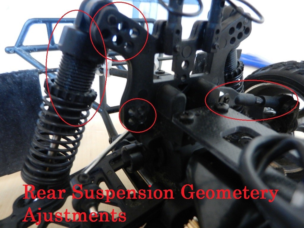
Rear Suspension Adjustments
The rear suspension plays a vital role in stability and traction. Several adjustable parts in the rear allow for precise tuning.
Adjustable Shocks (Spring Tension)
Adjusting the spring tension on your rear shocks changes the rear ride height and responsiveness. Tighter springs increase ride height and make the rear suspension stiffer, while looser springs lower the ride height and soften the suspension.
Shock Positions (Shock Angle & Ride Height)
Multiple shock positions on the rear shock tower allow you to alter both the shock angle and ride height. Moving the shocks to inner positions generally softens the suspension response, while outer positions stiffen it. This also affects the initial compression rate and how the car handles weight transfer.
Adjustable Upper Arms (Camber)
Adjustable upper arms let you modify the rear camber angle. Camber refers to the angle of the wheels relative to the vertical axis when viewed from the front or rear. Adjusting camber influences tire contact patch during cornering and straight-line stability.
Upper Arm Positions (Camber)
Similar to shock positions, different upper arm positions on the rear hub carrier can fine-tune camber. These positions offer subtle adjustments to optimize tire contact and grip based on track conditions.
Image: A close-up view highlighting the adjustable shocks and upper arms on the rear suspension of an RC car, showcasing the components discussed for camber and ride height adjustments.
Rear Hub Carrier Adjustments
The rear hub carrier provides additional points for fine-tuning suspension geometry.
Upper Arm Positions (Camber)
The rear hub carrier often features multiple upper arm positions, offering another way to adjust camber and further refine handling characteristics in the rear.
Lower Arm Positions (Ride Height)
Adjusting lower arm positions on the rear hub carrier allows for precise ride height adjustments. This is crucial for optimizing ground clearance and center of gravity, impacting both on-road and off-road performance.
Image: Detail of the rear hub carrier, pointing out the upper and lower arm positions that enable ride height and camber adjustments, important for tuning rear suspension.
Front Suspension Adjustments
The front suspension is critical for steering response and handling in corners. It also features several adjustable components.
Adjustable Shocks (Spring Tension)
Like the rear, the front shocks have adjustable spring tension. Adjusting front spring tension affects the front ride height and stiffness, influencing steering responsiveness and weight transfer during braking and acceleration.
Shock Positions (Shock Angle & Ride Height)
Front shock towers also have multiple positions for adjusting shock angle and ride height. Inner positions generally soften the front suspension, improving bump absorption, while outer positions stiffen it, enhancing steering response.
Adjustable Upper Arms (Camber)
Adjustable front upper arms allow for camber adjustments, similar to the rear. Front camber settings are crucial for steering precision and tire grip during cornering.
Upper Arm Positions (Camber)
Multiple upper arm positions on the front suspension provide further camber tuning options. These positions allow for fine-tuning the camber curve as the suspension compresses, optimizing tire contact throughout the suspension travel.
Adjustable Turn Buckles (Toe)
Front turnbuckles enable toe angle adjustments. Toe refers to the direction the front wheels point relative to each other. Toe-in means the front wheels point slightly inwards, enhancing straight-line stability. Toe-out means they point slightly outwards, improving turn-in response.
Adjustable Servo Saver (Servo Safety)
The servo saver protects your steering servo from damage during impacts. Adjusting the servo saver tension affects steering feel and responsiveness. A looser servo saver provides more protection but can feel less precise, while a tighter servo saver offers more direct steering but less protection.
Image: An overview of the front suspension, highlighting adjustable shocks, upper arms, turnbuckles, and servo saver, key elements for front suspension tuning.
Front Upper Arm Position Adjustment
Switching between front upper arm positions can be slightly intricate. The images below illustrate the process and provide a clearer understanding of the necessary steps for adjustment.
Image: Two images demonstrating the steps involved in adjusting the front upper arm positions, aiding users in understanding this potentially tricky adjustment.
Slipper Clutch Adjustment
The slipper clutch is a critical component in the drivetrain, managing power delivery and protecting gears.
Slipper Clutch Adjustment Screws
The slipper clutch is adjusted using two hex screws. These screws control the clutch’s slip, affecting how much power is transferred to the wheels and protecting the drivetrain from sudden shocks. Equal adjustments to these screws are essential for balanced performance.
Image: A close-up of the slipper clutch mechanism, clearly showing the two hex screws used for adjusting the amount of drivetrain slippage.
Sway Bar Adjustment
Sway bars, also known as anti-roll bars, influence body roll and handling during cornering.
Sway Bar Tension Screws
The front and rear sway bar backplates feature hex screws that adjust sway bar tension. These screws influence how much the sway bar resists body roll, impacting cornering characteristics and stability.
Image: Two images detailing the front and rear sway bar setups, pointing out the hex screws responsible for adjusting sway bar tension and influencing body roll.
Tuning Guide: Understanding Handling Effects
Now that you’re familiar with the adjustable parts, let’s explore how these adjustments affect your RC car’s handling. Understanding these effects is key to tuning your car for optimal performance in various conditions.
Quick Tuning Guide Table
This table provides a starting point for understanding how different adjustments can affect your RC car’s handling.
Image: A tuning guide table summarizing the effects of different suspension adjustments on handling characteristics, useful for quick reference during tuning.
Oversteer vs. Understeer
Understanding oversteer and understeer is fundamental to RC car tuning.
Image: A diagram illustrating the concepts of oversteer and understeer, essential for understanding vehicle dynamics and suspension tuning effects.
Oversteer occurs when the rear of the car loses traction and slides out, causing the car to turn more sharply than intended. Understeer happens when the front tires lose grip, and the car doesn’t turn as much as the driver intends, pushing wide in corners.
Basic Tuning Principles
Let’s explore some basic tuning principles to get you started.
Suspension Stiffness (Springs)
Spring Stiffness: Springs that are too stiff will cause the car to bounce excessively over bumps. Springs that are too soft will make the car wallow and feel unresponsive.
Front vs. Rear Springs: Softer front springs can increase front grip and lead to oversteer, as the rear becomes lighter. Softer rear springs promote understeer, a more predictable handling characteristic often preferred for beginners.
Ride Height Adjustment
Optimizing Ride Height: Generally, lower ride height improves handling by lowering the center of gravity. However, ride height must be balanced with ground clearance to avoid bottoming out on the terrain.
Aerodynamic Effects: A slightly lower front ride height than the rear creates a rake effect, improving aerodynamic downforce and reducing lift. Lower ride height also reduces drag and can improve battery efficiency.
Shock Tower Positions: Adjusting shock positions on the shock towers is the primary way to change ride height. Lowering ride height impacts suspension geometry and damping, requiring careful consideration of these effects.
Center of Mass
Weight Distribution: The center of mass significantly influences handling. Front-heavy cars tend to understeer, while rear-heavy cars tend to oversteer.
Weight Bias in Performance Cars: Sports and racing cars often favor a rearward weight bias (e.g., 40/60 or 35/65) to improve corner entry. This helps the front tires initiate rotation into a turn more effectively.
Adjusting Center of Mass: You can adjust your RC car’s center of mass by repositioning components like the battery, ESC (Electronic Speed Controller), and receiver.
Slipper Clutch Tuning
Slipper Clutch Function: The slipper clutch protects the drivetrain from impacts and allows for controlled wheelspin on slippery surfaces.
Slipper Clutch Adjustment: Adjust the slipper clutch to absorb jolts from jumps and prevent excessive wheelspin, especially on loose surfaces.
Advanced Tuning Techniques
Once you’ve mastered basic tuning, you can explore more advanced adjustments.
Camber Angle
Camber Explained: Camber is the angle of the wheel relative to vertical. Positive camber means the top of the wheel tilts outwards, while negative camber means it tilts inwards.
Camber and Handling: Camber significantly affects handling and tire wear, particularly during cornering. Optimal camber settings for handling may cause increased tire wear.
Toe Angle
Toe Explained: Toe refers to the direction the front wheels point relative to each other. Toe-in is when the front of the wheels points inwards, and toe-out is when they point outwards.
Toe and Stability: Toe-in improves straight-line stability, while toe-out enhances steering response. Toe settings are a balance between stability and agility. Rear toe is also adjustable on many RC cars, generally set with less angle than the front. Rear toe-out can cause oversteer and is rarely used in rear-drive race cars.
Damping (Shocks)
Damping Function: Dampers (often called shocks) work with springs to control suspension movement, manage oscillations, and maintain tire contact with the ground.
Damping Adjustment: Damping affects how quickly the suspension reacts to load changes. Heavier shock oil increases damping resistance and makes the suspension stiffer.
Damping and Handling: Stiffer front damping increases rear grip and understeer. Stiffer rear damping increases front grip and oversteer.
Shock Oil Change: For more in-depth damper tuning, changing the shock oil viscosity can fine-tune handling.
RC Shock Oil Change Video Tutorial
Video: Embedded YouTube video tutorial on how to change shock oil in Traxxas shocks, relevant for understanding damper tuning.
Shock Angle of Attack
Shock Angle and Performance: Shock angle, adjusted via shock tower positions, dramatically changes shock behavior under different forces.
Inner Shock Positions: Inner shock positions improve handling during cornering and reduce body roll by performing better under lateral forces.
Outer Shock Positions: Outer shock positions handle longitudinal forces better, improving performance over jumps and bumps, but can increase rollover risk.
Balancing Ride Height and Shock Performance: Changing shock positions affects both shock performance and ride height, requiring a balanced approach based on driving conditions.
Body Lean/Roll
Body Roll and Handling: Body roll occurs due to centrifugal forces during cornering. Suspension and anti-roll bars (sway bars) are designed to manage body roll and maintain tire contact.
Center of Mass Height: Lower center of mass reduces body roll and improves handling.
Controlling Body Roll: Springs, sway bars, and roll center height adjustments can all be used to control body roll.
Corner Balancing
Corner Balancing Concept: Corner balancing ensures each tire exerts equal force on the ground relative to the diagonally opposite tire, preventing instability.
Achieving Corner Balance: Scales are used under each wheel to measure corner weights. Perfect corner balance is achieved when the sum of left-front and right-rear weights equals the sum of right-front and left-rear weights.
Image: Diagram illustrating perfect corner balance, showing equal weight distribution across diagonally opposite wheels for optimal handling.
Example of Perfect Corner Balance: For a 900g car with a centered CG, each corner ideally applies 225g of force.
Ideal Corner Balance with Rearward CG: Even with a rearward center of gravity, corner balance can still be optimized.
Image: Diagram depicting ideal corner balance in a car with a rearward center of gravity, showcasing weight distribution adjustments for balanced handling.
Mastering RC car suspension tuning is an ongoing process of experimentation and refinement. By understanding these principles and adjustable components, you can significantly enhance your RC car’s performance and driving enjoyment.