Are you fascinated by remote control cars and curious about the technology that brings them to life? Many assume that delving into electronics and programming is daunting, requiring years of engineering expertise. However, the reality is much more accessible than you might think. As a car enthusiast, technician, and coding hobbyist, I can attest that combining these passions is incredibly rewarding. Like many, I fondly remember RC cars from childhood and have always wanted to build my own as an adult. With the rise of user-friendly platforms like Arduino and my growing coding skills, now is the perfect time to turn that dream into a tangible project.
This guide is designed to show you how to build an Arduino-based RC car from scratch, even if you have no prior experience in programming, Arduino, or electronics. While some background in these areas might be helpful, it’s certainly not a prerequisite. This project uses readily available and affordable components, emphasizing a minimalist approach and detailed code explanations. The principles you’ll learn here extend far beyond just RC cars, providing a solid foundation for various electronics and programming projects. Let’s get started and bring your own programmable RC car to life!
Materials You’ll Need
Before we dive into the building process, gather these materials. The goal is to use common, easily obtainable components, many of which you might already have at home.
- Arduino UNO: The brain of your RC car, responsible for processing commands and controlling the motors.
- RC Car Chassis Kit: Includes the base frame, wheels, and motors. Choose a kit that suits your budget and size preferences.
- Jumper Wires (Male-Male and Female-Male): For making electrical connections between components.
- Electrical Insulation Tape: To secure and insulate wiring connections.
- Bluetooth Module (HC-06 or HC-05): Enables wireless control of your RC car from your Android phone.
- DC Motor Controller (L298N): An essential component to drive the car’s motors efficiently from the Arduino.
- Power Bank with 2 USB Outputs: A convenient and rechargeable power source for both the Arduino and the motor controller.
- Piezo Buzzer: Optional, but adds fun sound effects to your RC car.
- Android Mobile Phone: To install the control application.
- PC with Arduino IDE Installed: For programming the Arduino board. You can download the Arduino IDE from the official Arduino website.
- ArduCar – Arduino RC Car Bluetooth Controller App: Available on the Google Play Store, or you can explore other compatible apps.
Step 1: Assembling the RC Car Chassis
Let’s begin by putting together the foundation of our RC car – the chassis. Most chassis kits come with their own assembly instructions, but here’s a general guide to help you through the process:
-
Prepare the Components: Lay out the main chassis frame, motor mounting brackets (usually small plastic pieces, four in total – two for each motor), screws, brass spacers, nuts, motors, and a spare USB cable. Also, have some jumper wires ready.
-
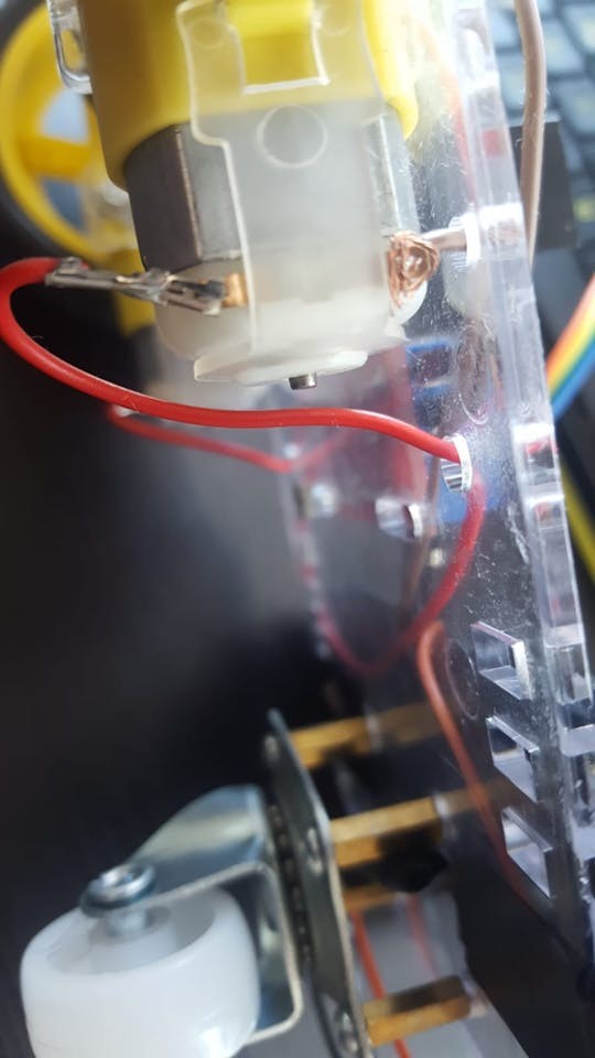
Connect Wires to Motors: For each motor, connect a wire to each of its pins. Soldering is ideal for a robust connection, but if you don’t have a soldering iron, you can securely twist or “knot” the wires to the pins. Ensure a firm connection for reliable power delivery.
-
Prepare the USB Cable for Power: Take an old USB cable and cut off one end, leaving about 20cm (around 8 inches) of cable with the USB connector.
-
Strip the USB Cable: Carefully strip a few centimeters of the outer cable sheath to expose the internal wires. You should find 4 or 5 wires inside, but we only need the red (positive – Plus) and black (ground – GND) wires. Strip about 2-4 cm of insulation from the ends of both the red and black wires. You can reinforce these connections by twisting them with longer, stronger jumper wires or soldering them for added durability.
-
Mount Motors to Chassis: Attach the motors to the chassis frame using the plastic brackets, screws, and nuts. Most motors have a small dot on one side; ensure these dots face inwards towards each other when you mount the two motors. This orientation is often important for consistent motor direction.
-
Install Supporting Wheel Spacers: Locate the four small holes near the end of the chassis frame, usually arranged in a square pattern. These are for the third, supporting nylon wheel. Use the brass spacers and screws to mount them in these holes, ensuring the spacers are on the same side of the frame as the motors.
-
Mount Supporting Wheel: Attach the nylon supporting wheel to the brass spacers using screws. This wheel provides stability and balance to your RC car.
-
Attach Wheels to Motors: Push the wheels onto the motor shafts. Note the shape inside the wheel hub; align it correctly with the motor shaft for a proper fit. You might encounter some resistance, but apply firm, gentle pressure until the wheels are securely in place.
-
Mount Arduino and Motor Controller: Position the Arduino module and DC motor controller on the chassis frame. Use the remaining screws and nuts from your kit to secure them. If needed, use electrical insulation tape to protect any exposed wires and ensure components are stable.
Step 2: Wiring the Electronics
With the chassis assembled and components mounted, it’s time to connect everything. Prepare your male-male and female-male jumper wires. Careful wiring is crucial for the RC car to function correctly.
-
Connect Motors to Motor Controller: Attach the wires from the motors to the DC motor controller’s output terminals. The L298N motor controller typically labels these as OUT1, OUT2, OUT3, and OUT4. For wiring consistency, let’s define the pin assignments as follows:
- OUT1: Left motor (-) GND wire
- OUT2: Left motor (+) wire
- OUT3: Right motor (+) wire
- OUT4: Right motor (-) GND wire
Ensure you connect the positive and negative motor wires correctly to control direction properly.
-
Connect Arduino to Motor Controller (Control Signals): Now, we need to connect the Arduino to the motor controller to send control signals. Use jumper wires to connect the following pins:
- L298N IN1 to Arduino Digital Pin 5
- L298N IN2 to Arduino Digital Pin 6
- L298N IN3 to Arduino Digital Pin 10
- L298N IN4 to Arduino Digital Pin 11
These IN pins on the motor controller will receive signals from the Arduino to dictate motor direction and speed. Female-male jumper wires are ideal here, but you can modify male-male wires or solder if needed.
-
Connect Bluetooth Module: The Bluetooth module allows wireless communication with your Android phone. Most Bluetooth modules like HC-06 or HC-05 have four pins labeled VCC, GND, TXD, and RXD. Connect them as follows:
- Bluetooth VCC to Arduino 5V pin (Power)
- Bluetooth GND to Arduino GND pin (Ground)
- Bluetooth TXD to Arduino Digital Pin 0 (RXD – Receive Data)
- Bluetooth RXD to Arduino Digital Pin 1 (TXD – Transmit Data)
Notice that the TXD and RXD pins are cross-connected – the transmitter of one device connects to the receiver of the other, and vice versa.
-
Connect Piezo Buzzer (Optional): If you’re adding a piezo buzzer for sound effects, it has two legs: a longer Anode (+) and a shorter Cathode (-). Connect them like this:
- Piezo Buzzer Anode (+) (Longer leg) to Arduino Digital Pin 3
- Piezo Buzzer Cathode (-) (Shorter leg) to Arduino GND pin (Ground)
While a 330 Ohm resistor is often recommended between the piezo buzzer and the Anode pin to limit current, it’s optional for basic sound effects and might make the buzzer quieter.
-
Powering the Motor Controller: Use the USB cable you prepared earlier. Connect the red wire (+) and black wire (-) to the DC motor controller’s power input terminals. These are typically labeled for 12V and GND.
- USB Red wire (+) to L298N 12V input
- USB Black wire (-) to L298N GND input
-
Powering the Circuit: Finally, connect two USB cables to your power bank. One cable will power the Arduino, and the other will power the DC motor controller via the USB cable you just connected. Plug the USB connector of the prepared USB cable into one output of the power bank, and another USB cable into the second power bank output, connecting the other end to the Arduino’s USB port. Mount the power bank securely to the chassis using electrical tape or another mounting method. Some power banks require you to press a power button to activate the USB outputs.
Step 3: Programming Your RC Car with Arduino
Now for the exciting part – programming the Arduino to control your RC car! You’ll need the Arduino IDE software installed on your computer.
- Set Up Arduino IDE: Open the Arduino IDE. Go to “Tools” in the menu bar. Select “Board:” and choose your Arduino board (likely “Arduino UNO”). Then, go to “Port:” and select the USB port your Arduino is connected to. If the “Port” option is greyed out, connect your Arduino to your computer via USB; it should become available. You might need to try different USB ports on your computer until the correct one is recognized.
-
Upload the Code: You have two options to get the code into your Arduino:
- Option 1: Open and Upload the Code File: Download the provided Arduino code file (if available). Open it in the Arduino IDE and click the “Upload” button (usually a right arrow icon).
- Option 2: Copy and Paste the Code: If you only have the code text, in the Arduino IDE, go to “File” -> “New” to create a new sketch. Copy the code provided below and paste it into the new sketch window. Then, click the “Upload” button.
Important Note: Before uploading, disconnect the Bluetooth module’s RX (Digital 0) and TX (Digital 1) wires from the Arduino. These pins are used for communication with your computer during code upload, and interference from the Bluetooth module can prevent successful uploading. Reconnect them after the code is uploaded.
Here’s the Arduino code you’ll need to upload:
#define in1 5
#define in2 6
#define in3 10
#define in4 11
int state;
int piezo = 3;

void setup() {
  pinMode(in1, OUTPUT);
  pinMode(in2, OUTPUT);
  pinMode(in3, OUTPUT);
  pinMode(in4, OUTPUT);
  pinMode(piezo,OUTPUT);
  Serial.begin(9600);
}

void loop() {
  if (Serial.available() > 0) {
    state = Serial.read();
    Stop();
    switch (state) {
      case 'F': forward(); soundFX(3000.0,30+400*(1+sin(millis()/5000))); break;
      case 'G': forwardleft(); soundFX(3000.0,60); break;
      case 'D': forwardright(); soundFX(3000.0,60); break;
      case 'N': backright(); soundFX(3000.0,30+100*(1+sin(millis()/2500))); break;
      case 'C': backleft(); soundFX(3000.0,30+100*(1+sin(millis()/2500)));
                  soundFX(3000.0,30+100*(1+sin(millis()/2500)));
                  soundFX(3000.0,30+100*(1+sin(millis()/2500)));
                  soundFX(3000.0,30+100*(1+sin(millis()/2500))); break;
      case 'B': back(); soundFX(3000.0,30+200*(1+sin(millis()/2500)));
                  soundFX(3000.0,30+200*(1+sin(millis()/2500)));
                  soundFX(3000.0,30+200*(1+sin(millis()/2500)));
                  soundFX(3000.0,30+200*(1+sin(millis()/2500))); break;
      case 'L': left(); soundFX(3000.0,60);
                  soundFX(3000.0,60);
                  soundFX(3000.0,60);
                  soundFX(3000.0,60); break;
      case 'R': right(); soundFX(3000.0,60);
                  soundFX(3000.0,60);
                  soundFX(3000.0,60);
                  soundFX(3000.0,60); break;
      case 'H': soundFX(3000.0,30+200*(1+sin(millis()/2500)));
                  soundFX(3000.0,60);
                  soundFX(3000.0,30+200*(1+sin(millis()/2500)));
                  soundFX(3000.0,60);
    }
  }
}

void forward() {
  analogWrite(in1, 255);
  analogWrite(in3, 255);
}

void forwardleft() {
  analogWrite(in1, 50);
  analogWrite(in3, 255);
}

void forwardright() {
  analogWrite(in1, 255);
  analogWrite(in3, 50);
}

void back() {
  analogWrite(in2, 255);
  analogWrite(in4, 255);
}

void backright() {
  analogWrite(in2, 50);
  analogWrite(in4, 255);
}

void backleft() {
  analogWrite(in2, 50);
  analogWrite(in4, 50);
}

void left() {
  analogWrite(in4, 255);
  analogWrite(in1, 255);
}

void right() {
  analogWrite(in3, 255);
  analogWrite(in2, 255);
}

void Stop() {
  analogWrite(in1, 0);
  analogWrite(in2, 0);
  analogWrite(in3, 0);
  analogWrite(in4, 0);
}

void soundFX(float amplitude,float period){
 int uDelay=2+amplitude+amplitude*sin(millis()/period);
 for(int i=0;i<200;i++){
  digitalWrite(piezo, HIGH);
  delayMicroseconds(uDelay);
  digitalWrite(piezo, LOW);
  delayMicroseconds(uDelay);
 }
}-
Reconnect Bluetooth and Power Up: After successful code upload, reconnect the Bluetooth module’s RX (Digital 0) and TX (Digital 1) wires to the Arduino. Also, reconnect the USB cable (Arduino to Power bank) to power up the Arduino from the power bank.
-
Install and Use the Control App: Download and install the “ArduCar – Arduino RC Car Bluetooth Controller” app from the Google Play Store on your Android phone. Launch the app, connect to your RC car’s Bluetooth module (you may need to pair them in your phone’s Bluetooth settings first – default pairing code is often 1234 or 0000). Now you should be able to control your RC car wirelessly using the app!
Congratulations! You’ve built and programmed your own Arduino-controlled RC car.
Step 4: Understanding the Arduino Code (Optional)
For those interested in understanding how the code works, here’s a breakdown of the Arduino program:
Arduino code is based on a simplified version of C/C++. Every Arduino program has two main sections: setup() and loop().
-
void setup() { }: This section runs only once when the Arduino starts. It’s used to initialize settings.pinMode(in1, OUTPUT);and similar lines: These lines configure the Arduino pins (in1, in2, in3, in4, piezo) as OUTPUT pins. This means the Arduino will send signals out from these pins to control other components (motor controller and buzzer).Serial.begin(9600);: This line starts serial communication at a baud rate of 9600. Serial communication is used to exchange data via the Bluetooth module. 9600 baud is a common and reliable rate for Bluetooth modules.
-
void loop() { }: This section runs repeatedly in a continuous loop as long as the Arduino is powered.if (Serial.available() > 0): This checks if there is any data available to be read from the serial port (i.e., from the Bluetooth module).state = Serial.read();: If data is available, this line reads the incoming byte and stores it in thestatevariable. Thisstatevariable will hold the command sent from your Android app.Stop();: This function (explained later) immediately stops the car’s motors to ensure it doesn’t keep moving unintentionally before a new command is processed.switch (state) { ... }: Thisswitchstatement checks the value of thestatevariable and executes different actions based on the received command character.case 'F': forward(); soundFX(...); break;: If the received character is ‘F’ (for Forward), it calls theforward()function to move the car forward and also plays a sound effect usingsoundFX(). Similarcasestatements handle commands like ‘B’ (Back), ‘L’ (Left), ‘R’ (Right), and combinations like ‘G’ (Forward-Left), ‘D’ (Forward-Right), ‘C’ (Back-Left), ‘N’ (Back-Right), and ‘H’ (special sound effect). Thebreak;statement is crucial to exit theswitchblock after acaseis executed.
-
Function Definitions (after
loop()): These functions define the actions for each command.void forward() { ... },void back() { ... },void left() { ... },void right() { ... },void forwardleft() { ... },void forwardright() { ... },void backleft() { ... },void backright() { ... },void Stop() { ... }: These functions control the motors. They useanalogWrite(pin, speed)to set the speed of each motor.analogWrite()sends a PWM (Pulse Width Modulation) signal, which effectively controls motor speed from 0 (stop) to 255 (full speed). By controlling thein1,in2,in3, andin4pins connected to the motor controller, we can control the direction and speed of the left and right motors independently, achieving different movements.void soundFX(float amplitude, float period) { ... }: This function generates sound effects using the piezo buzzer. It creates a square wave with a frequency and duration determined by theamplitudeandperiodparameters. This code is adapted from online Arduino sound effect examples and creates a Sci-Fi-like sound.
This code provides a basic framework for RC car control. You can expand upon it to add more features, control schemes, or sensor integrations.
Bluetooth Module Configuration (Optional)
HC-05 and HC-06 Bluetooth modules usually work out of the box with default settings (like 9600 baud rate). However, if you want to customize settings like the Bluetooth module’s name or pairing password, you can configure them using Arduino. This typically involves:
- Connecting Bluetooth Module for Configuration: You might need to connect the Bluetooth module to different Arduino pins and potentially use voltage dividers (resistors) as Bluetooth modules often operate at 3.3V logic levels, while Arduino operates at 5V.
- Uploading Configuration Code: You’d upload a specific Arduino sketch designed to send AT commands to the Bluetooth module for configuration.
- Using Serial Monitor: You’d use the Arduino IDE’s Serial Monitor to send AT commands and receive responses from the Bluetooth module to change its name, password, baud rate, etc.
Detailed tutorials on configuring HC-05/HC-06 Bluetooth modules with Arduino are widely available online if you wish to explore this further.
We hope this guide has empowered you to build and program your own RC car. Feel free to experiment with the code, add new features, and customize your project. Share your creations and any questions you have in the comments below!