Understanding HVAC wiring diagrams is crucial for troubleshooting and installing heating and cooling systems. This guide breaks down how to read a simple schematic wiring diagram, explaining common symbols and their functions. We’ll focus on the ladder diagram, a clear and concise way to visualize electrical circuits in HVAC systems.
HVAC systems rely on intricate wiring to control various components. Understanding these diagrams, specifically schematic diagrams or ladder diagrams, is essential for technicians to diagnose issues and ensure proper system operation. These diagrams simplify complex systems, providing a visual representation of the electrical connections and the flow of power.
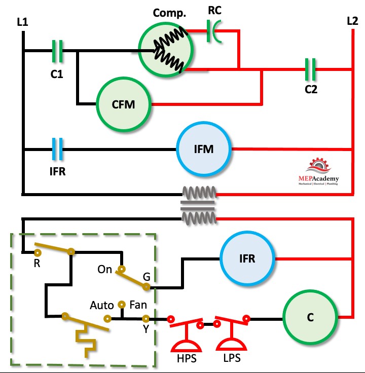
Decoding the Ladder Diagram: Key Components and Symbols
A ladder diagram gets its name from its resemblance to a ladder, with two vertical lines representing the power supply (L1 and L2) and horizontal rungs representing individual circuits. Let’s break down the common symbols you’ll encounter:
- Power Supply (L1 and L2): These vertical lines represent the incoming hot wires providing 208/230 volts, typically single-phase power.
- Transformer: This component reduces the line voltage to a safer 24 volts for controlling low-voltage devices like thermostats and relays. The symbol resembles two coils side-by-side.
- Thermostat: Represented by a switch-like symbol, the thermostat acts as the control center, signaling other components based on temperature settings.
- Relays: These electromechanical switches use a low-voltage signal to control high-voltage components. The symbol often includes a coil and a set of contacts.
- Contacts: Shown as lines that open or close, contacts control the flow of electricity within a circuit. Normally Open (NO) contacts are open until activated, while Normally Closed (NC) contacts are closed until activated.
- Motors: Symbols for motors often resemble a circle with an “M” inside, representing components like the compressor, condenser fan, and indoor blower motor.
- Capacitors: These components store electrical energy and are essential for starting and running motors. Their symbols often resemble two parallel lines.
- Safety Devices: Components like high and low-pressure switches protect the system from damage. These are often represented by specialized symbols indicating their function.
How a Simple HVAC System Works: Following the Circuit
In a typical air conditioning system, the thermostat sends a low-voltage signal to the compressor relay when cooling is needed. This energizes the relay’s coil, closing its contacts and allowing line voltage to power the compressor and condenser fan motor. Simultaneously, another relay activates the indoor blower motor to circulate cool air. When the desired temperature is reached, the thermostat breaks the circuit, de-energizing the relays and turning off the components.
From Schematic to Pictorial: Troubleshooting in the Real World
While the schematic diagram provides a functional understanding, a pictorial diagram shows the physical layout of components within the unit. Technicians often use both: the schematic for understanding the circuit logic and the pictorial for locating specific components.
Conclusion: Mastering Simple HVAC Wiring Diagrams
Understanding Simple Hvac Wiring Diagrams, particularly the ladder diagram, empowers technicians to effectively diagnose and repair system malfunctions. By recognizing key symbols and understanding how they interact, professionals can ensure efficient operation and maintain optimal comfort. Learning to interpret these diagrams is fundamental for anyone working with HVAC systems.