A VEC (Variable Electronic Control) sensor fault can significantly impact the performance of your electric bike or scooter. This guide delves into the common causes of Vec Sensor Faults, how to diagnose them, and potential solutions.
A VEC controller utilizes Hall sensors to detect the motor’s position and speed, ensuring smooth operation. If the throttle signal voltage is outside the expected range, usually between ~0.8V at rest and ~3.5V at full throttle, the controller will trigger a fault and prevent the motor from running. This safety mechanism protects the motor from accidental starts and potential damage. A throttle voltage of around 3V at startup is likely too high, causing the controller to remain in a safety mode. The motor should typically begin running when the throttle voltage falls below approximately 1V.
Understanding VEC Sensor Function and Fault Indications
Hall sensor throttles generally output a signal voltage of about 0.8V at rest. The motor typically starts turning at approximately 1.25V and achieves maximum RPM at around 3.5V. Any deviation from this range indicates a potential issue.
A common indication of a VEC sensor fault is an error code, often displayed as flashing lights on the controller. Additionally, the motor might not run, run erratically, or experience reduced power. A malfunctioning throttle or wiring issues can often cause these symptoms.
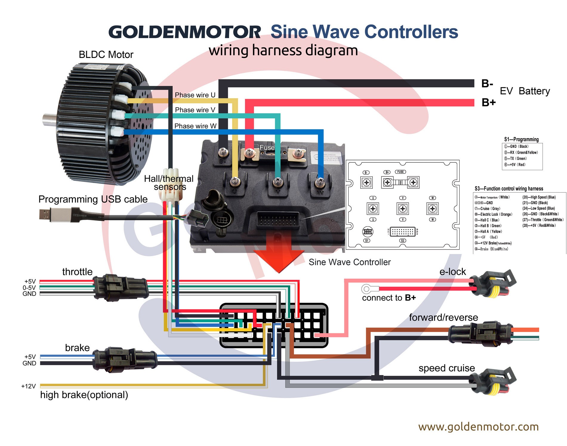
Figure 1: VEC Controller Wiring Diagram. Ensure all connections are secure and correctly placed.
Diagnosing a VEC Sensor Fault
Troubleshooting a VEC sensor fault involves a systematic approach:
-
Visual Inspection: Begin by thoroughly inspecting all wiring connections to the controller, particularly the Hall sensor wires and the three-phase motor wires, ensuring they are correctly and securely fastened to their corresponding terminals. Refer to the controller’s wiring diagram for accurate placement.
-
Voltage Measurement: If the visual inspection reveals no apparent problems, utilize a voltmeter to test the Hall sensor signal voltages. Each sensor should fluctuate between approximately 0V and 4.5V relative to ground (battery negative) as the motor is manually rotated. Each sensor should cycle High and Low four times per complete revolution of the motor shaft. This confirms proper sensor function. A consistent low or high voltage reading indicates a faulty sensor or wiring issue.
-
Throttle Functionality: Check the throttle mechanism itself. A potentiometer throttle should exhibit a smooth change in resistance, while a Hall effect throttle’s voltage should vary proportionally with throttle position.
Common Causes and Solutions for VEC Sensor Faults
Several factors can contribute to a VEC sensor fault:
-
Loose or Damaged Wiring: This is a frequent culprit. Carefully examine all wiring connections for looseness, damage, or corrosion. Repair or replace any faulty wiring.
-
Faulty Hall Sensor: If the voltage test reveals a problem with a specific Hall sensor, replacement is necessary.
-
Controller Malfunction: Although less common, the VEC controller itself can malfunction. If all other components check out, the controller might require replacement.
-
Incorrect Throttle Type Selection: When using an Arduino board with your controller, ensure you have selected the correct throttle type (Hall effect or Potentiometer) in your setup. An incorrect setting can lead to operational issues.
Conclusion
A VEC sensor fault can be frustrating, but with careful diagnosis and troubleshooting, the issue can often be resolved. By following the steps outlined in this guide, you can pinpoint the source of the problem and implement the appropriate solution. Remember to consult your controller’s documentation for specific troubleshooting instructions and error codes.